Flush-to-grade vault with wall-mounted cross-connect panels

a cross-connecting panel and vault technology, applied in the field of electrical and related telecommunication equipment housing, can solve the problems of high installation cost, liability, and box number, and achieve the effect of reducing the installation cos

Inactive Publication Date: 2005-03-01
STOCKDALE COMM CROSS CONNECT SYST
View PDF33 Cites 18 Cited by
  • Summary
  • Abstract
  • Description
  • Claims
  • Application Information

AI Technical Summary

Benefits of technology

is to remedy the problems of the prior art noted above. In particular, an object of the invention is to provide a housing (vault) for cross-connect equipment that minimizes the cost of installing, protecting and servicing the equipment.

Problems solved by technology

The boxes present a number of problems.
First, they are an eyesore to an already cluttered urban landscape.
Second, they are a liability issue as they typically encroach on pedestrian sidewalks.
Third, since they are located at street corners they are the unintended targets of vehicles that routinely run them over, knocking out telephone service for local customers and costing the telephone companies a lot of money to repair.
The problem is that you cannot simply lower the contents of the cabinet into an underground vault.
The cost of such a vault is prohibitive, not to mention the fact that there is not enough space on the street corners where the telephone companies have existing easements.
The problem with this design is meeting telephone company requirements for failure testing of the telephone cables that get flexed when the panel pops up.
To date no one has come up with a solution for this cable stress.
In addition there is some concern about panel frames accidentally releasing during servicing of the equipment and trapping or injuring a technician.

Method used


Image

  • Flush-to-grade vault with wall-mounted cross-connect panels
  • Flush-to-grade vault with wall-mounted cross-connect panels
  • Flush-to-grade vault with wall-mounted cross-connect panels

Examples


Embodiment Construction

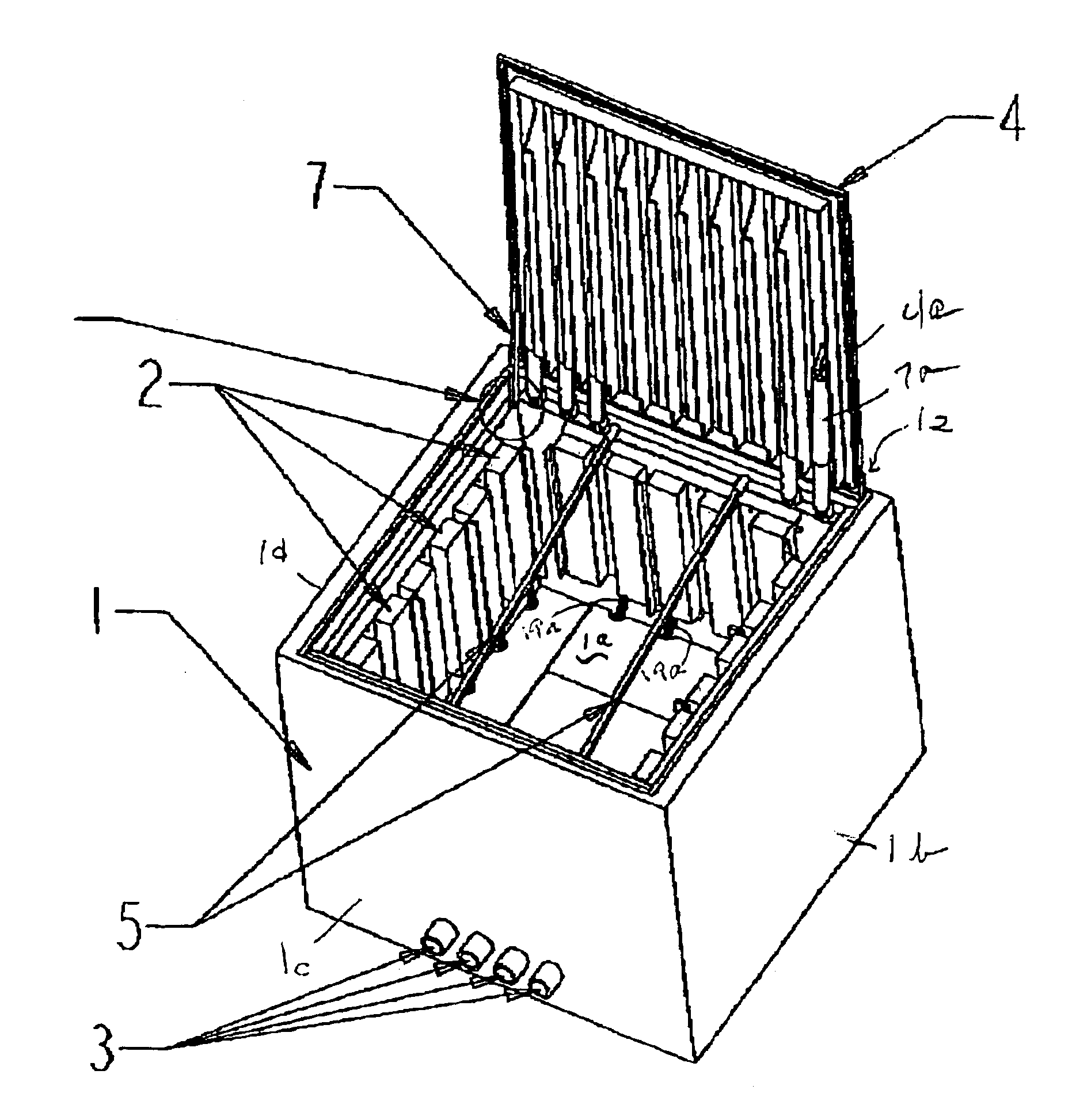
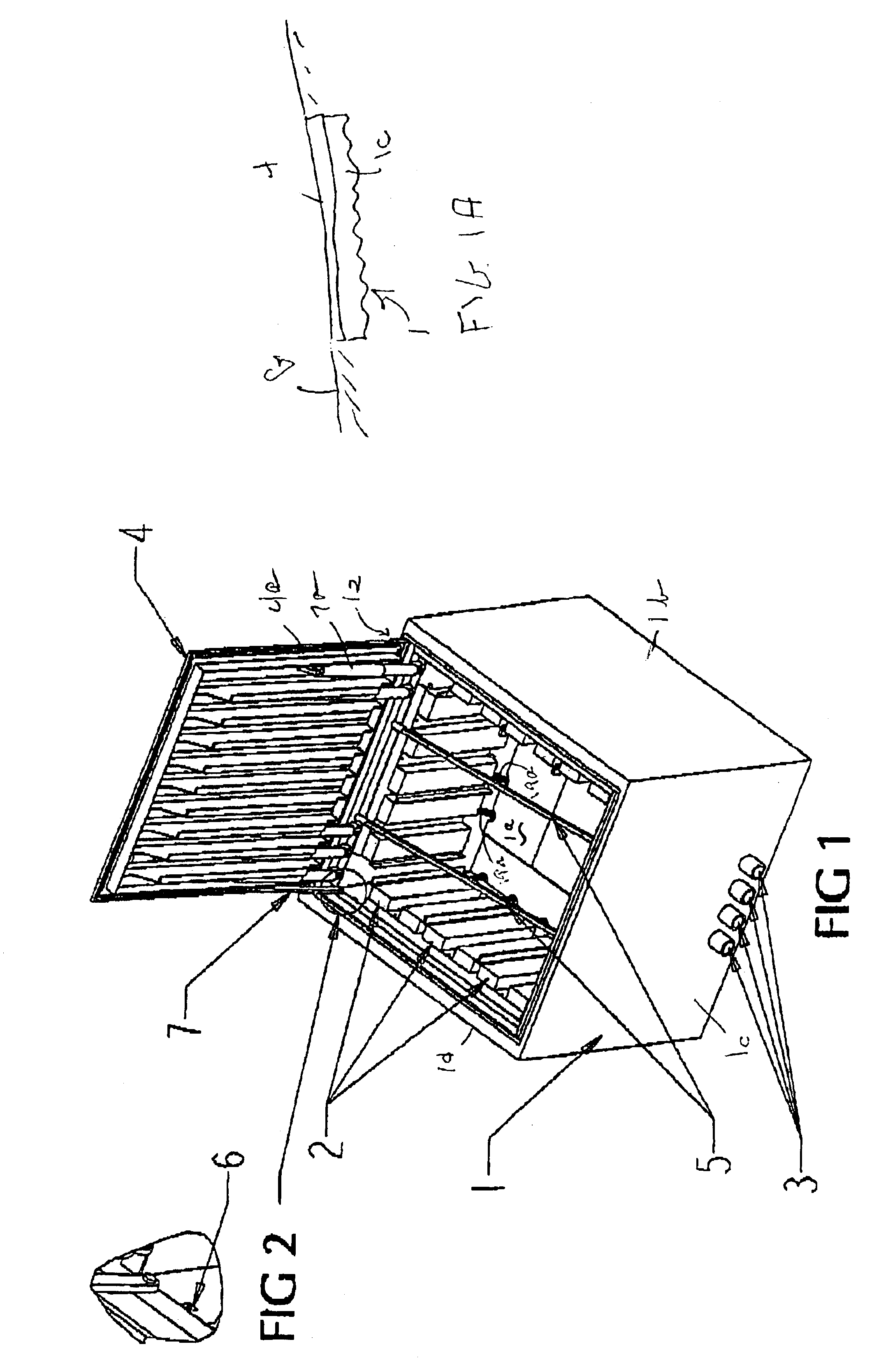
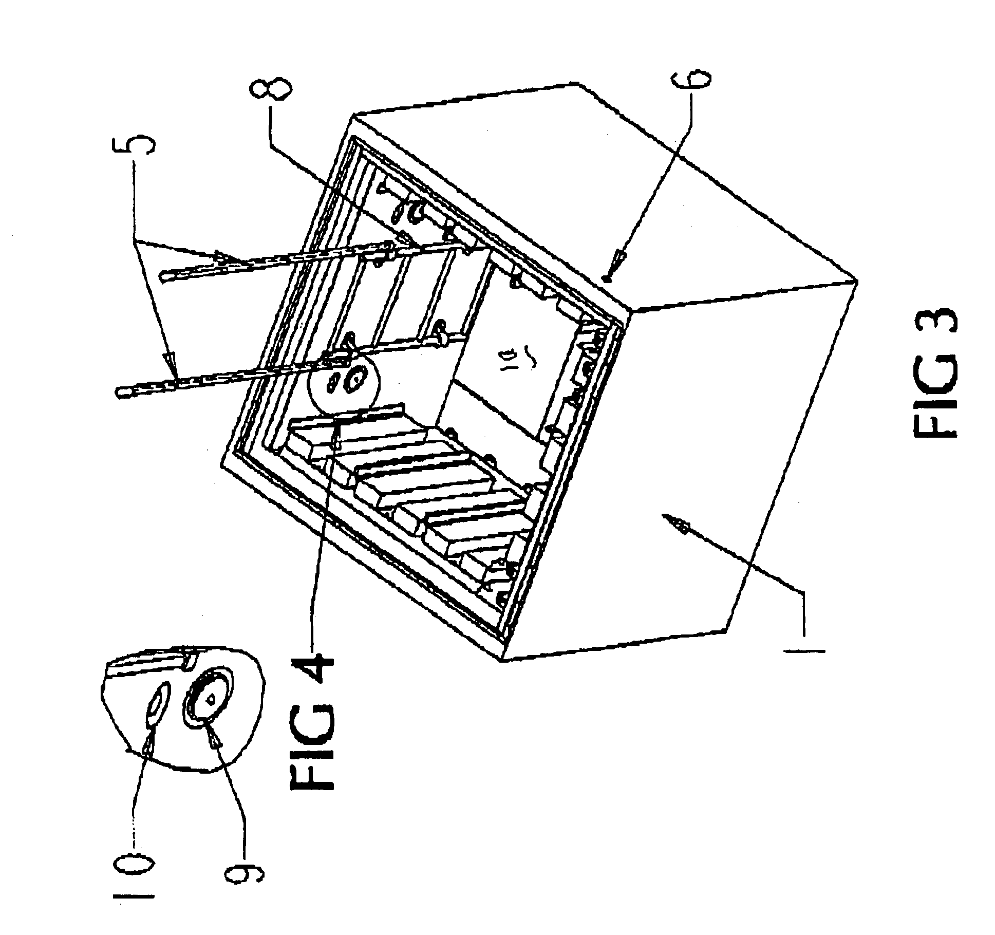
FIG. 1 shows a housing or vault 1 constructed in accordance with the invention. It is constructed for mounting in the ground G (FIG. 1A) and is formed with at least one wall defining an interior space 1a. The vault 1 can in principle be spherical or cylindrical or have another shape but in the preferred embodiment comprises rectangular (possibly though not necessarily square) side walls 1b, 1c, 1d and 1e, a top or cover 4, and a bottom 1f (FIG. 6).

At least one cross-connect panel is mounted on at least one of the walls. Preferably, a plurality of such panels 2 are mounted on a plurality of the walls. The cross-connect panels 2 respectively comprise frames and blocks and are mounted in stationary relation with respect to the walls of the housing or vault 1. Once installed, the conductors never need to be flexed during their entire service life.

Ducts 3 are provided for leading cables 19 (FIG. 6) through a wall of the vault and into the interior space 1f. Floor covers 11 (FIG. 5) enabl...


PUM


Abstract

A vault is contructed for mounting in the ground and formed with at least one wall defining an interior space. At least one cross-connect panel is mounted on the wall in stationery relation thereto. Signal conductors are attached to the panel and extend through the wall. A top cover enables ingress to and digress from the interior space by service personnel.

Description

BACKGROUND OF THE INVENTION1. Field of the InventionThis invention relates to housings for electrical and related telecommunication equipment. More particularly, it relates to a novel and highly effective vault that affords easy servicing of such equipment and maximum protection of the equipment between visits by service personnel, and that can be accommodated within the space provided by existing easements for such equipment.2. Description of the Prior ArtCross-connect equipment is standard in the telephone industry and well known to those skilled in the art. It is described in numerous patents and other printed documents and available from a number of commercial sources. The present invention is not characterized by the details of such equipment.Telephone companies have for years struggled with the fact that on about every street corner in the US and other countries there is a large gray box or cabinet that houses telephone cross connect equipment. The boxes present a number of pr...

Claims


Application Information

Patent Timeline
Patent Type & Authority Patents(United States)
IPC IPC(8): H02G9/00H02G9/10
CPCH02G9/10
Inventor HUTCHIN, SCOTT W.HENRY, JR., RONNIE B.DIAZ, HENRY
Owner STOCKDALE COMM CROSS CONNECT SYST
Why Eureka
Try Eureka