Guarded tub enclosure

a tub enclosure and guarding technology, applied in the direction of electronic circuit testing, measurement devices, instruments, etc., can solve the problem of difficult to maintain a controlled environment within the outer shield

Inactive Publication Date: 2005-03-01
FORMFACTOR INC
View PDF15 Cites 63 Cited by
  • Summary
  • Abstract
  • Description
  • Claims
  • Application Information

AI Technical Summary

Problems solved by technology

One drawback of the probe station 11 depicted in FIG. 2 is that the large space enclosed by the outer shield box

Method used


Image

  • Guarded tub enclosure
  • Guarded tub enclosure
  • Guarded tub enclosure

Examples


Embodiment Construction

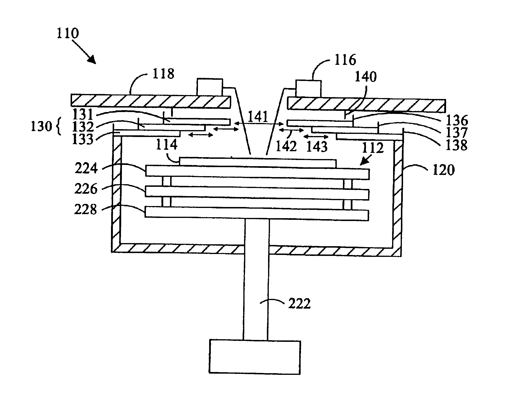
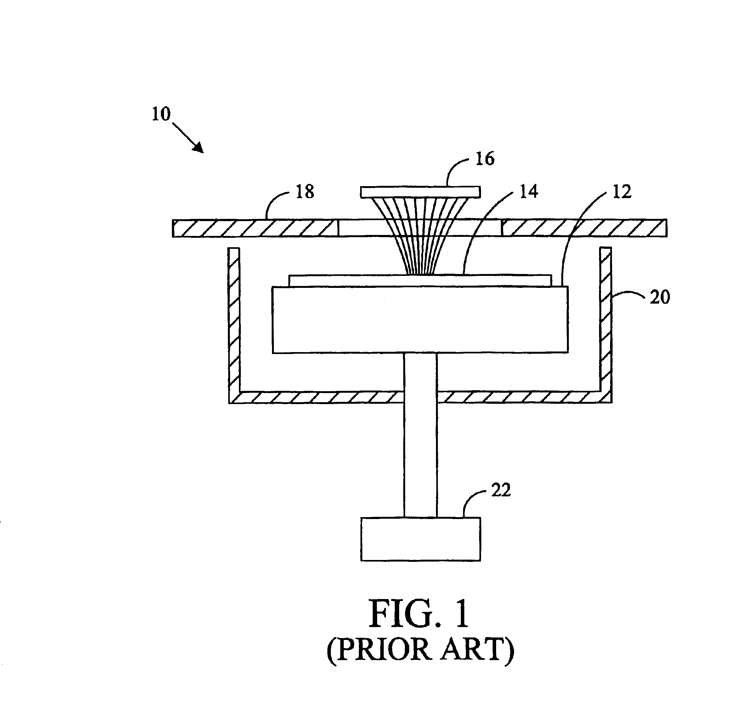
Referring again to FIG. 1, the probe station 10 having a chuck 12 that does not laterally move with respect to the tub enclosure 20 permits a small region immediately surrounding the chuck 12 to be enclosed. During testing the chuck 12 and enclosure 20 are moved laterally relative to the probes 16. The relatively small environment of the enclosure 20 facilitates efficient management of the environment within the enclosed region. The tub enclosure 20 defines an upper opening typically at least as large as the wafer including the electrical devices to be tested so that each electrical device may be successively positioned beneath the probing apparatus 16 by lateral movement of the chuck 12 and tub enclosure 20.

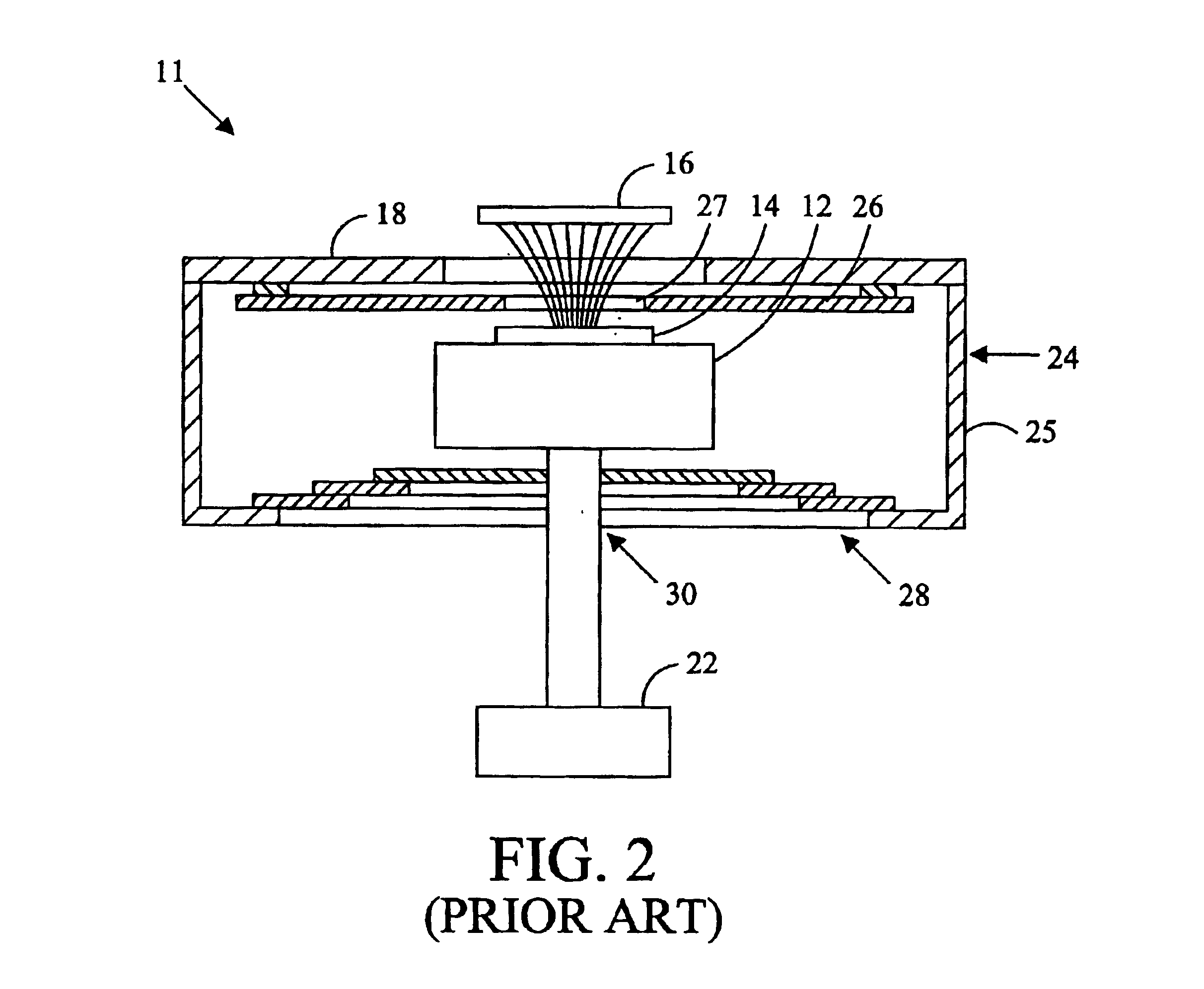
Referring to FIG. 2, the inclusion of a conductive member electrically connected to a guard potential vertically spaced above the chuck 12 of the probe station 10 provides for a quiet electrical environment surrounding the chuck 12, as exemplified in U.S. Pat. No. 5,266,889 and ...


PUM


Abstract

A probe station with an improved guarding structure.

Description

BACKGROUND OF THE INVENTIONThe present invention relates to a guarding structure for a probe station.Probe stations are designed to measure the characteristics of electrical devices such as silicon wafers. Probe stations typically include a chuck that supports the electrical device while it is being probed by needles or contacts on a membrane situated above the chuck. In order to provide a controlled environment to probe the electrical device, many of today's probe stations surround the chuck with an environmental enclosure so that temperature, humidity, etc. may be held within predetermined limits during testing. Environmental enclosures protect the device from spurious air currents that would otherwise affect measurements, and also facilitate thermal testing of electrical devices at other-than-ambient environmental conditions. Environmental conditions within the enclosure are principally controlled by a dry air ventilation system as well as a temperature element, usually located b...

Claims


Application Information

Patent Timeline
IPC IPC(8): G01R31/28G01R1/02G01R1/18
CPCG01R31/2886G01R31/2862G01R1/18G01R31/2865
Inventor DUNKLEE, JOHNNORGDEN, GREGCOWAN, C. EUGENE
Owner FORMFACTOR INC
Why Eureka
Try Eureka