Method and apparatus for solar energy storage system using gas and rock

a technology of solar energy storage and solar energy, which is applied in the direction of lighting and heating equipment, machines/engines, greenhouse gas reduction, etc., can solve the problems of not being economical for power gird energy storage, short life, unfriendly to the natural environment, etc., and achieves continuous electric power generation, low cost, and high quality

Inactive Publication Date: 2008-03-20
ZHU YANONG
View PDF20 Cites 149 Cited by
  • Summary
  • Abstract
  • Description
  • Claims
  • Application Information

AI Technical Summary

Benefits of technology

[0014]A method and Apparatus for solar energy storage system uses gas for thermal transport and uses rock for thermal storage medium

Problems solved by technology

None of them can meet the large-scale power grid storage requirements for low cost, less location dependency, high reliability, high efficiency, and environment friendly.
The lead acid battery is not economical for power gird energy storage plus the short lifetime and un-friendly to natural environment.
Flywheel has limited capacity, cost, and reliability issue when apply to large-scale grid power storage.
Pumped water hydro power plant is the most practical way for large grid scale energy storage, but the a

Method used


Image

  • Method and apparatus for solar energy storage system using gas and rock
  • Method and apparatus for solar energy storage system using gas and rock
  • Method and apparatus for solar energy storage system using gas and rock

Examples


Embodiment Construction

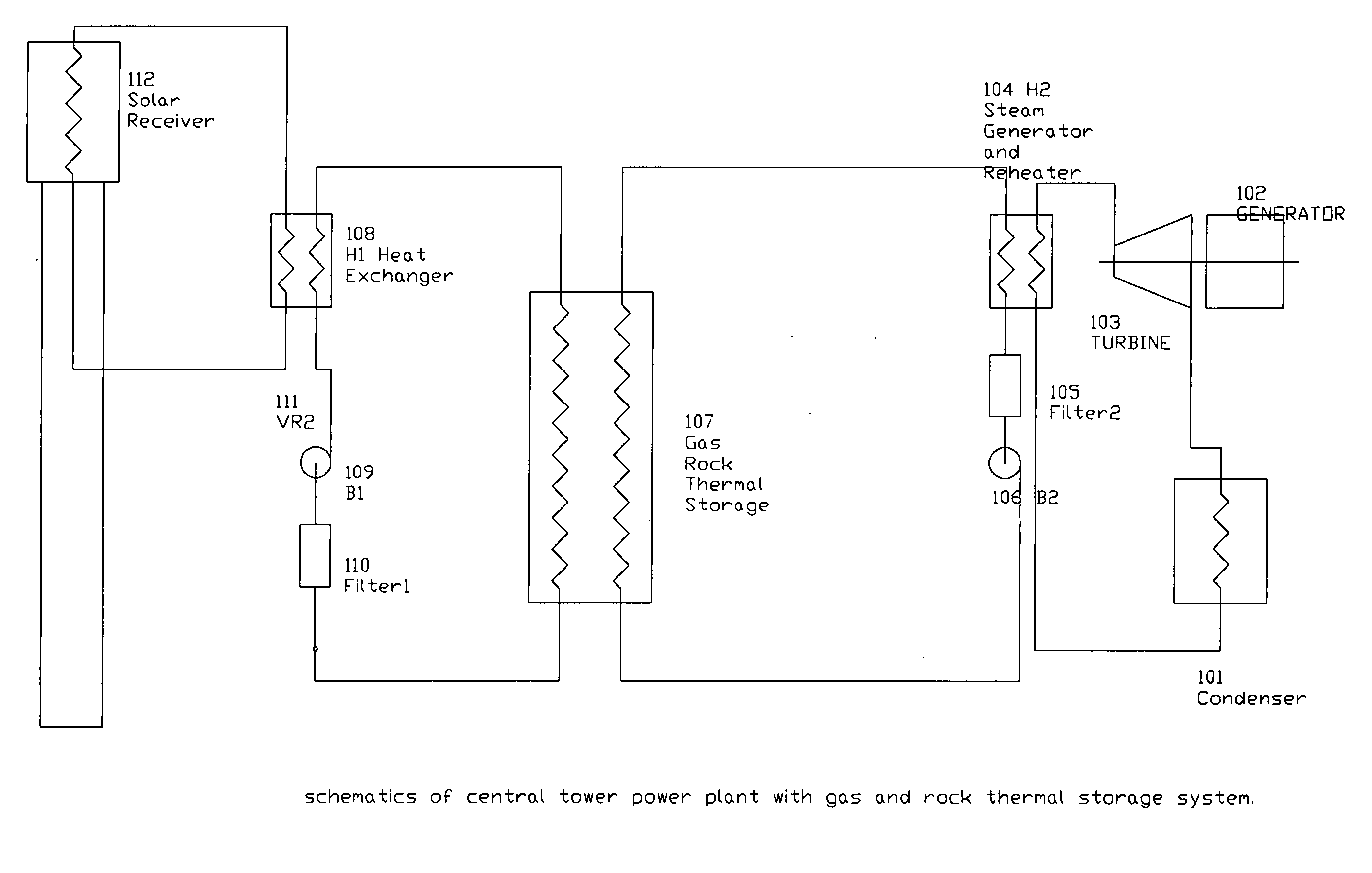
[0027]This invention is generally related to a method and Apparatus for solar energy storage system uses gas for thermal transport and uses rock for thermal storage medium for central tower solar thermal electric power plant to provide high quality, low cost, and continuously electric power generation.

[0028]The thermal storage system as illustrated by FIG. 1 contains the thermal charge system 112,108,109, and 110, and the thermal discharge system 104,105, and 106, and the thermal storage modules 107.

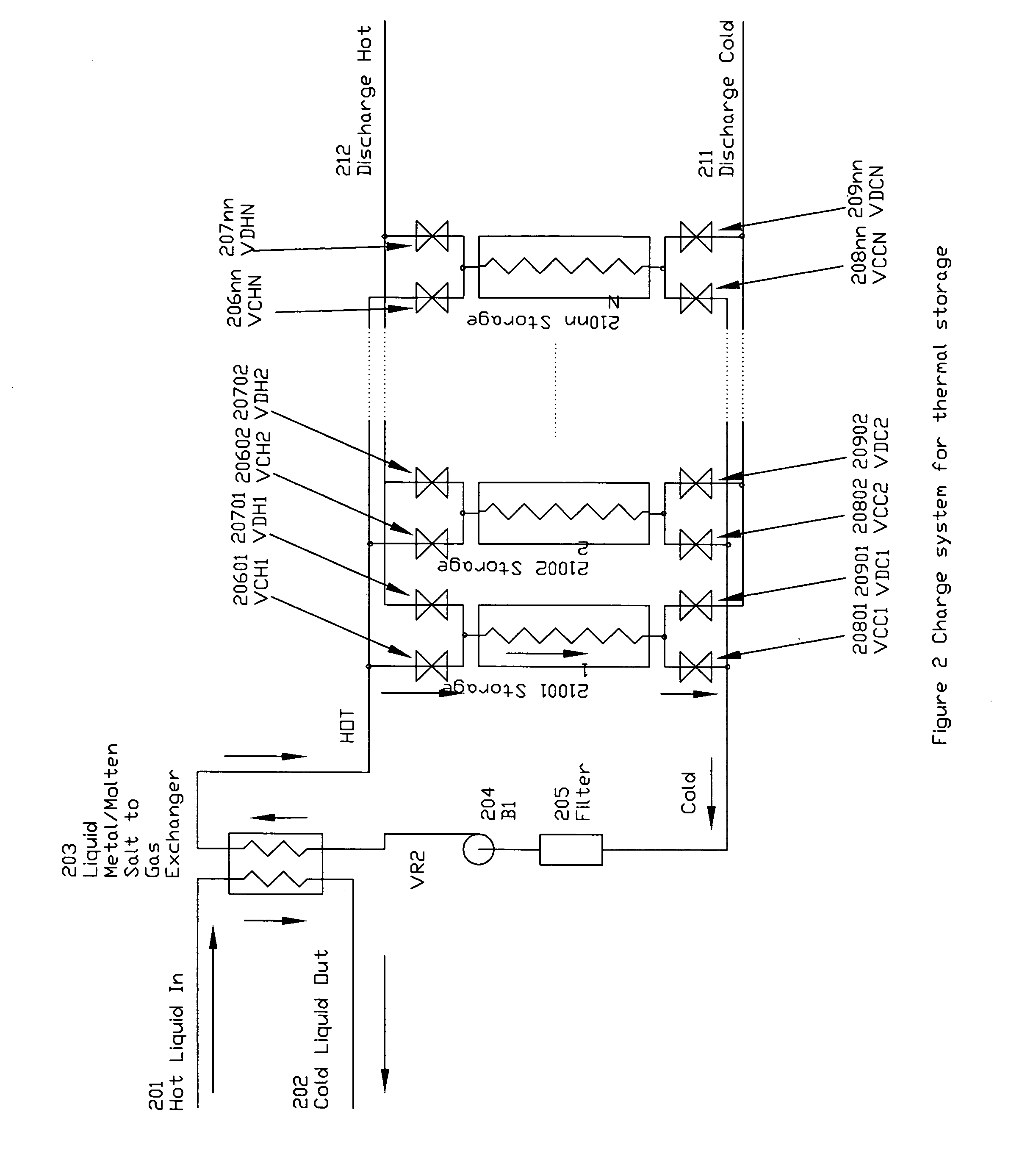
[0029]The thermal charge system charges the thermal storage modules while the discharge system discharge the thermal storage modules. A thermal storage module is connected to charge system for charge and connected to discharge system for discharge. The valves connected at the hot end and the cold end of a thermal storage module can switch the connections of the storage module between the charge and discharge system following the controls of the thermal storage system controller.

[0030]The...


PUM


Abstract

A method and Apparatus for solar energy storage system uses gas for thermal transport for central tower solar thermal electric power plant to provide high quality, low cost, and continuously electric power generation. The storage contains a number of storage modules that each module can store energy for a given period of time. The thermal energy from central tower charges the modules one by one during the sunny time, while the thermal electric power plant discharge the modules one by one as long as it works. A control and a connection valve system control and connect the charge and discharge modules with the central tower and the power plant according to pre-arranged sequences. Fans at the cool side of the storage system push the circulation gas into the central tower or the thermal storage modules. In the discharge system, the hot gas from storage system is send to the heat exchange system, and to generate steam and to super heat steam for the power plant. In the charge system, the cold gas is pushed into the central receiver thermal exchange unit and to be heated, and the hot gas is then circulated back to storage system to charge up the storage system.

Description

BACKGROUND OF THE INVENTION[0001]1. Field of the Invention[0002]This invention generally relates to solar thermal energy storage by using rock or other type of solid storage media and use gas, liquid metal, and steam as the thermal transfer media.[0003]2. Description of Prior Art[0004]The differences between the nature characters of the solar energy and power grid requirement require thermal storage to buffer and temperature store energy. The nature characters of the solar energy are not service on demand while the power grid requires backbone power plant supply electricity to the grid must be service on demand. The solution for meeting the service on demand requirements is the thermal energy storage system.[0005]The thermal energy storage system stores the excessive thermal energy to thermal storage during sunshine time and less electric demanding time, and release the stored thermal energy when the power plant is demanding.[0006]In additional to meet the requirement of service on ...

Claims


Application Information

Patent Timeline
IPC IPC(8): F24J2/34
CPCF03G6/005F03G6/065F24J2/07Y02E70/30F28D20/0056Y02E10/46Y02E60/142F24J2/4649F24S80/20F24S20/20Y02E60/14
Inventor ZHU, YANONG
Owner ZHU YANONG
Why Eureka
Try Eureka