
Communication and control network for distributed power resource units

Inactive Publication Date: 2005-04-19
ABB POWER GRIDS SWITZERLAND AG
View PDF53 Cites 149 Cited by
  • Summary
  • Abstract
  • Description
  • Claims
  • Application Information

AI Technical Summary

Benefits of technology

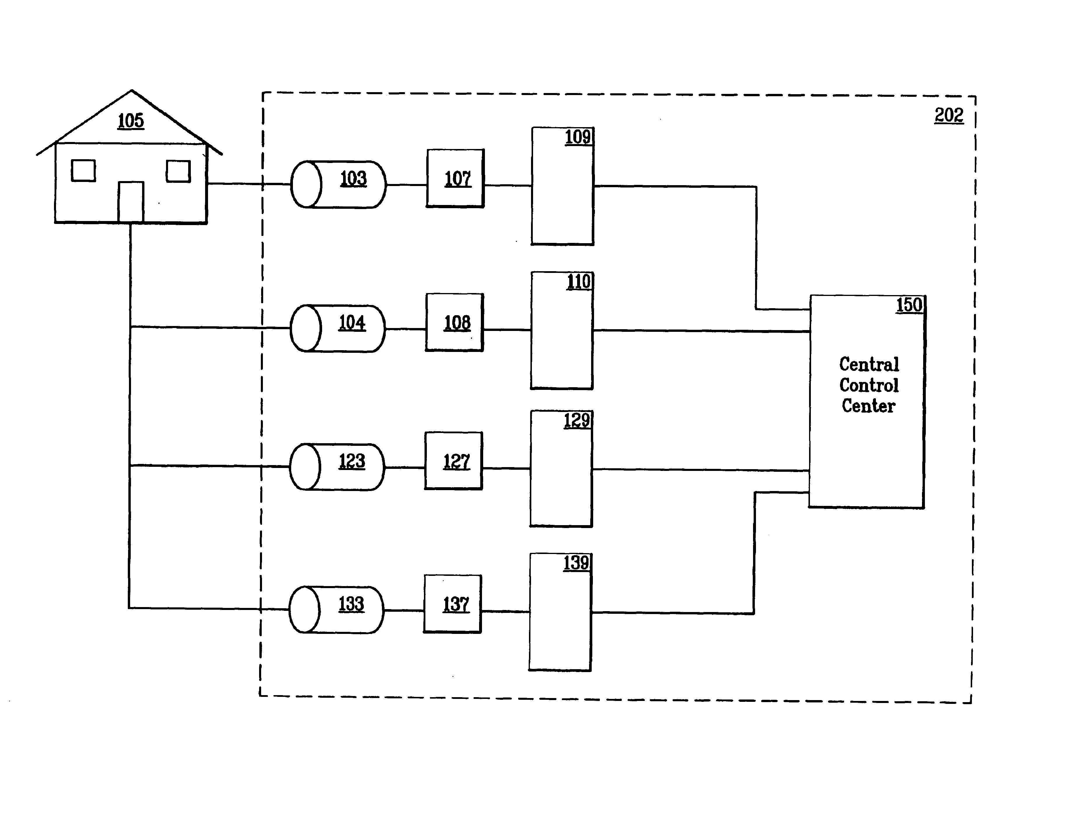
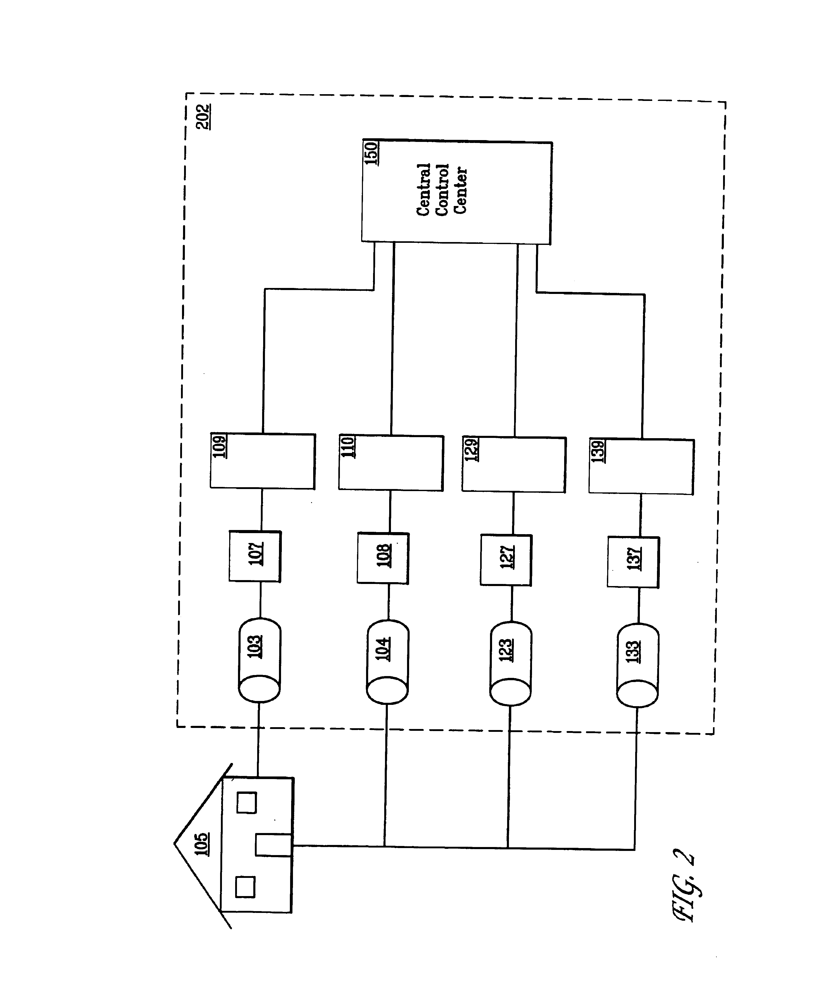
[0019]The disclosed invention, a communications and control management system for electric power assets (generators and storage devices) satisfies the aforementioned need in the art by disclosing a micro-grid including multiple distributed resource assets (e.g. distributed generation and storage) connected by a communications network to a central management and control center so that the operation of the assets can be coordinated and the aggregate of assets can be operated as a single plant. The management and control center receives operation and performance data from a plurality of electric power devices, and data concerning current electric power requirements and manages

Problems solved by technology

This evolution is a result of drawbacks in the generation of power by large centralized power stations, of changes in the regulation of the electrical industry and of technological advances in the development of different types of small power generators and storage devices.
There are numerous disadvantages to these traditional power plants.
Most of these plants have outputs of more than 100 megawatts (MW), making them not only physically large but also complex in terms of the facilities they require.
Site selection and procurement are often a real challenge because of this.
Ofen no sites are available in the area in which the plant is needed, or ordinances are in effect (such as no high voltage power lines are permitted in certain areas) that make acquisition of an appropriate site difficult.
There is considerable public resistance on aesthetic, health and safety grounds, to building more large centralized power plants, especially nuclear and traditional fossil-fueled plants.
High voltage transmission lines are very unpopular.
Long-distance electricity transmission via high voltage power lines has considerable environmental impact.
Long distance transmission of electricity is expensive, representing a major cost to the end-user because of investment required in the infrastructure and because losses accrue in the long-distance transmission of electricity proportionate to the distance traveled so that additional electricity must be generated over that needed to handle the power needs of the area.
Plant efficiency of older, existing large power plants is low.
To exacerbate the matter, typical large central plants must be over-designed to allow for future capacity, and consequently these large central plants run for most of their life in a very inefficient manner.
This is often an expensive and inefficient process.
Some areas are too remote to receive electricity from existing transmission lines, requiring extension of existing transmission lines, resulting in a corresponding increased cost for electric power.

Method used


Image

  • Communication and control network for distributed power resource units
  • Communication and control network for distributed power resource units
  • Communication and control network for distributed power resource units

Examples


Embodiment Construction

Overview

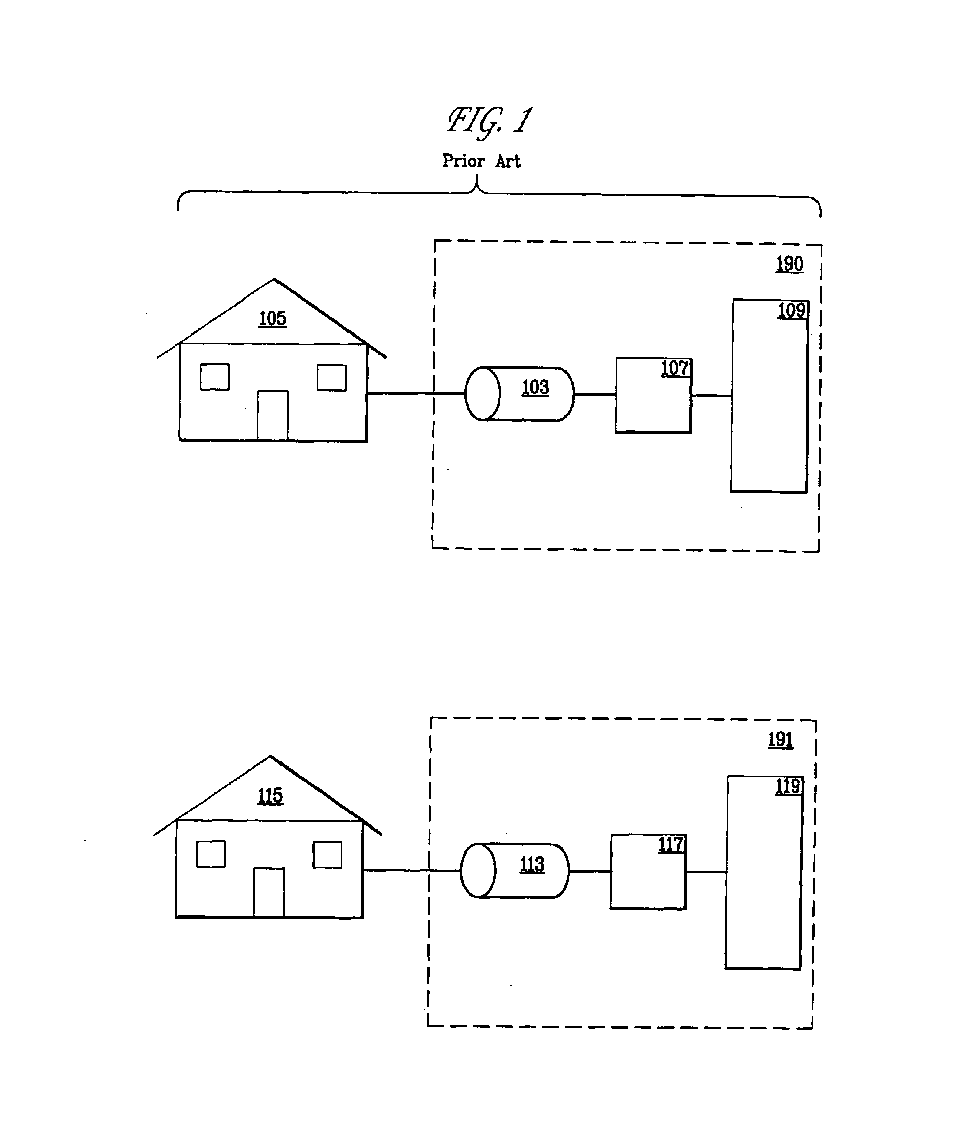
[0029]As can be seen from FIG. 1, distributed generation is any small-scale power generation technology 103, 113 that provides electric power at a site closer to customers' premises 105, 115 than central station generation. The small-scale power generators 103, 113 may be interconnected to the distribution system, “the grid” (not shown) or may be connected directly to a customer's premise or facility, 105, 115. To control a distributed generator 103, 113, distributed generator 103, 113 is connected to a controller 107, 117 that is connected to a communications device 109, 119. Communications device 109, 119, (for example, a modem), and controller 107, 117, (for example, a conventional programmable logic controller (PLC)) are well known in the art.

[0030]As can be seen from FIG. 1, distributed generator 103 cannot be used to provide electricity to customer premise 115 and distributed generator 113 cannot be used to provide electricity to customer premise 105. Likewise controll...


PUM


Abstract

Methods and systems are disclosed for managing a plurality of power resource assets from a central control center, operating the plurality of power resource assets in an automated fashion as a single power plant.

Description

[0001]This application is a continuation of Ser. No. 09 / 752,574 filed Dec. 29, 2000, now abandoned, the entirety of which is incorporated herein by reference.TECHNICAL FIELD[0002]This invention relates to the field of communications and control. In particular, the invention is directed to the management of distributed power resource systems through an automated communications and control system.BACKGROUND OF THE INVENTION[0003]As computing was done in the 1960's with powerful, central computers connected to remote terminals, so traditionally electrical power has been produced by large centralized power stations that generate electricity and transmit the electricity over high-voltage transmission lies. The voltage is then stepped-down in several stages and distributed to the customer. But just as the mainframes of the 1960's were superseded by the desktop PC, and then by networked computers and Web-based information systems, so electrical power distribution systems are evolving. This...

Claims


Application Information

Patent Timeline
IPC IPC(8): H02J3/30H02J3/32H02J3/28H02J13/00
CPCH02J3/28H02J3/30H02J3/32H02J13/0006H02J2003/003Y04S10/54Y02E60/16Y02E60/722Y04S10/14Y04S20/221Y02B70/3216H02J3/003Y02B70/30Y02E60/00Y04S10/50Y04S20/222Y02B70/3225H02J3/381H02J13/00028Y04S10/12Y02E40/70
Inventor PETRIE, EDWARD M.LEVANDER, HANSWILLIS, H. LEESTILLMAN, HAROLD M.
Owner ABB POWER GRIDS SWITZERLAND AG
Learn More