Test socket

a test socket and socket technology, applied in the field of test sockets, can solve the problems of unstable axial alignment of conventional test sockets, and achieve the effect of improving the testing of the device under tes

Inactive Publication Date: 2005-03-01
TATE JOHN O
View PDF20 Cites 49 Cited by
  • Summary
  • Abstract
  • Description
  • Claims
  • Application Information

AI Technical Summary

Benefits of technology

It is an object of the test socket disclosed herein to provide stable axial alignment in order to improve the testing of the device under test, and to provide a direct electrical path from the device under test to the printed circuit board. The test socket preferably includes a contactor having a distal end which is received within a retainer having a tapered inner diameter for guiding the distal end of the contactor, and into a terminal housing which includes a counterbore such that movement

Problems solved by technology

While generally acceptable, conventional test sockets do not maintain stable axial alignment, i.e. perp

Method used


Image

  • Test socket
  • Test socket
  • Test socket

Examples


Embodiment Construction

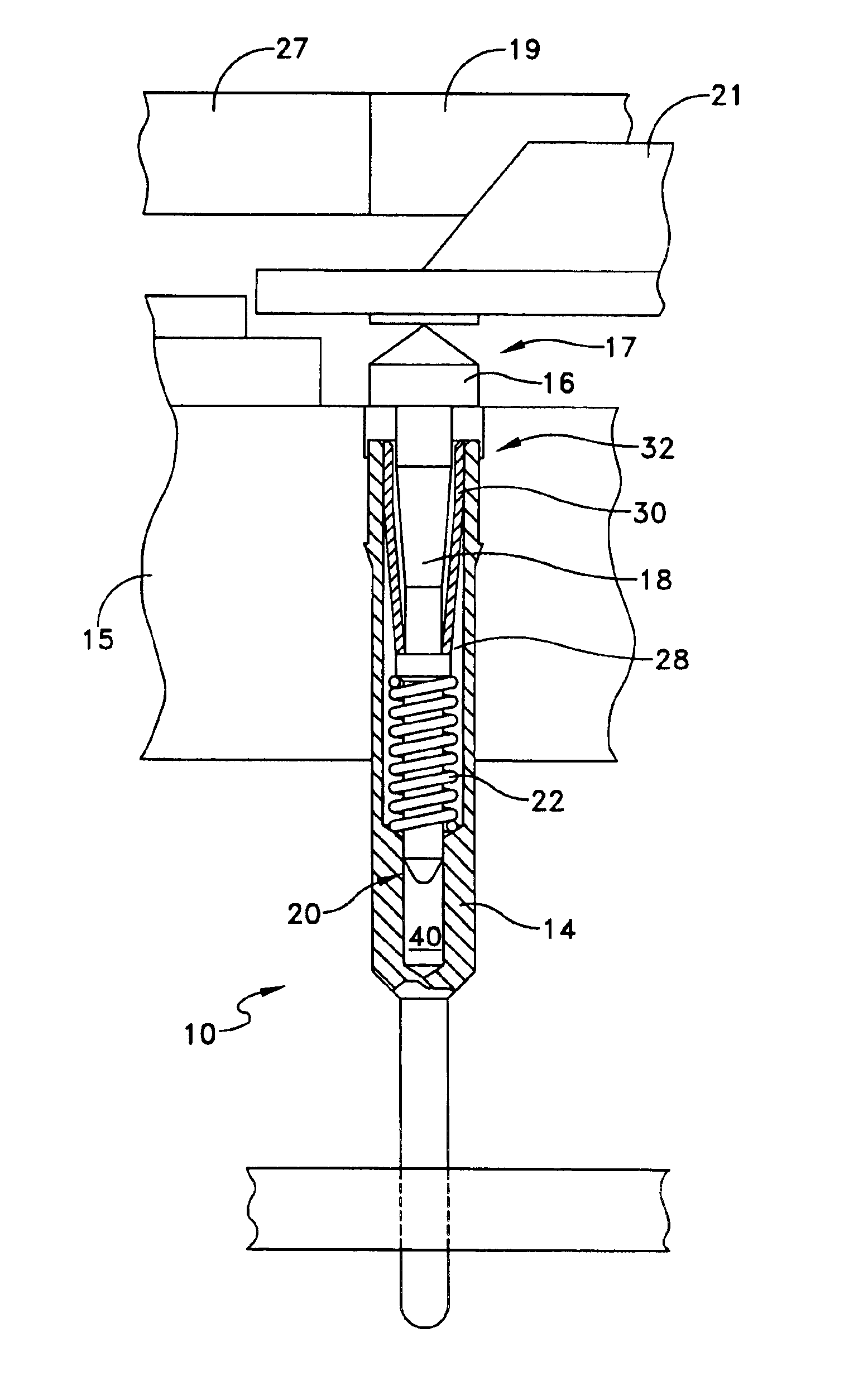
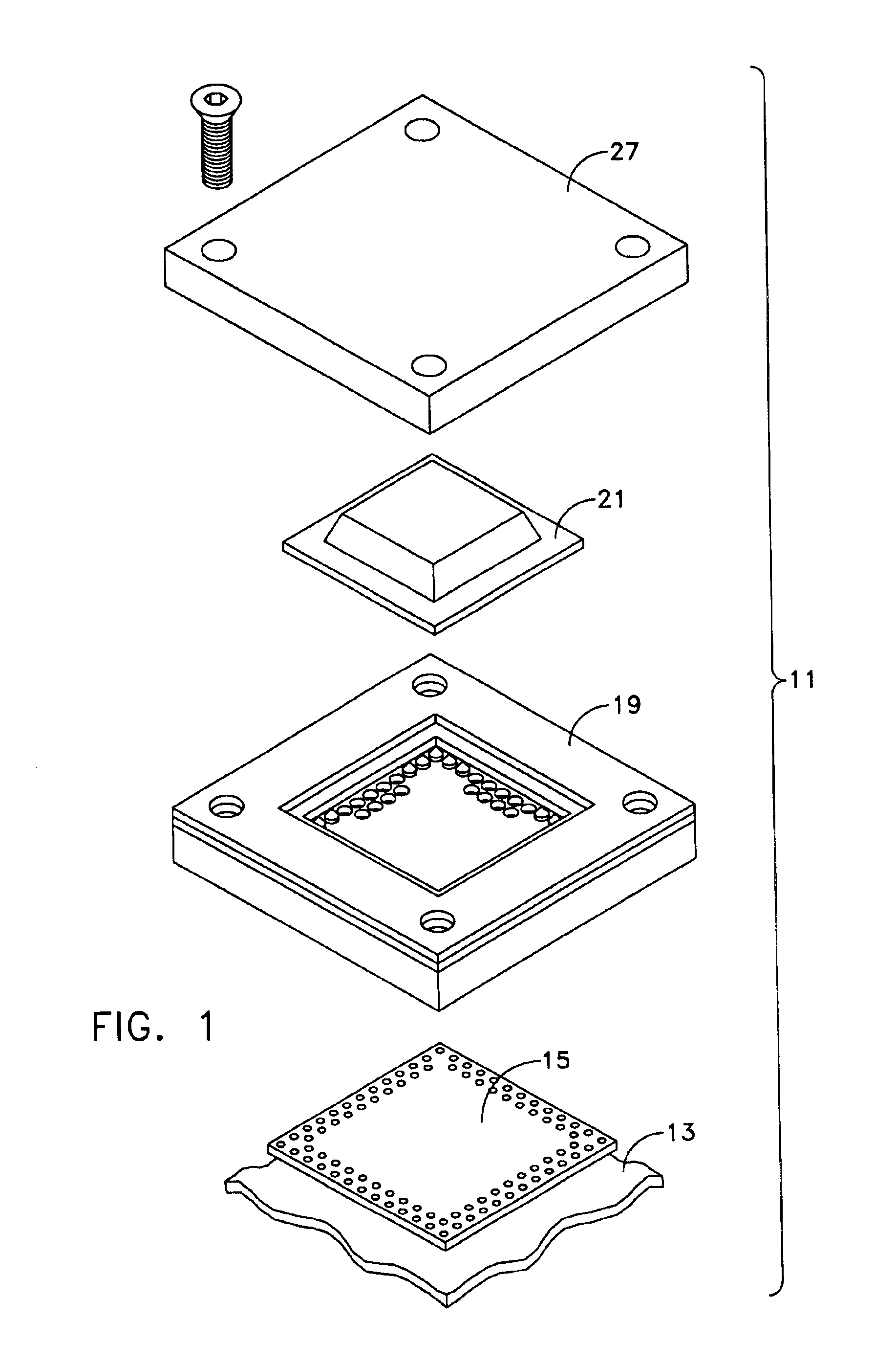
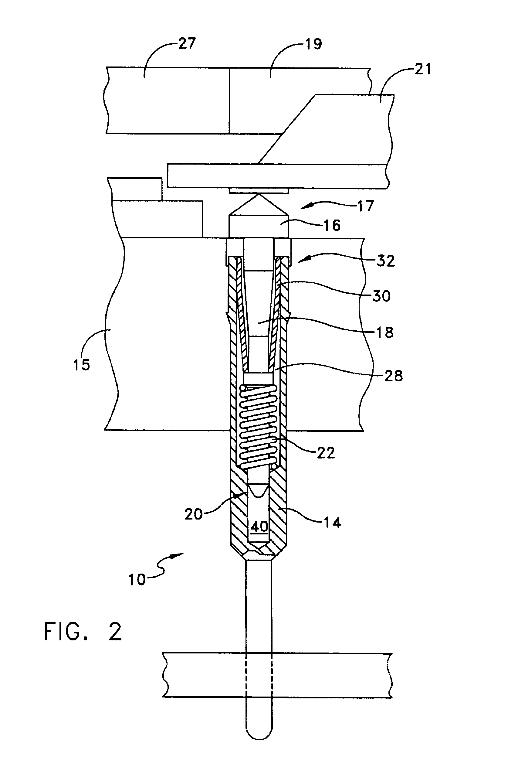
Referring now to the Figures, an improved test socket 10 including a contactor assembly 12 and a terminal housing 14 for use with test assembly 11 is shown. Test assembly 11 may be any conventional test assembly including, for example, a printed circuit board 13, an insulator base 15, a guide 19, a device under test 21, and a cover 27, as is conventional. In use, the contactor assembly 12 is disposed within the terminal housing 14 such that the contactor moves substantially in an up and down, or axial direction (arrow “A”, FIG. 6), so as to maintain the contactor substantially perpendicular with respect to the test assembly, as described in greater detail below. In addition, the contactor assembly is in electrical contact with the terminal housing 14, so that a direct electrical path is formed between the device under test (DUT) and the printed circuit board, without the primary electrical path going through spring 22 of the contactor assembly, as also described in greater detail be...


PUM


Abstract

A test socket including a contactor having a distal end which is received within a tapered retainer for guiding the distal end of the contactor and into a terminal housing having a counterbore such that movement of the distal end of the contactor is restricted by the counterbore of the terminal is disclosed.

Description

DESCRIPTION1. Technical FieldThe invention relates generally to a test socket, and more particularly to a test socket which has improved axial alignment and which provides a direct electrical path from a device under test to a printed circuit board.2. Background of Related ArtIt is well known in the art to use test sockets for the testing of electronic circuits. Conventional test sockets have a plurality of contactors, springs and retainers which are assembled into a terminal that forms the conductive element of the test socket. An insulator is also generally provided consisting of a base into which the contactor assembly is held. A guide accurately positions the device under test (DUT), which also may include devices such as a ball grid array (BGA), land grid array (LGA), and a column grid array (CGA). A cover is also provided, which is attached to the guide and base after the DUT is placed on top of the base; and several devices are provided for compressing the cover on top of the...

Claims


Application Information

Patent Timeline
IPC IPC(8): G01R1/02G01R1/04G01R1/067H01R13/24H01R13/22
CPCG01R1/0466G01R1/0483G01R1/06722H01R13/2421H01R2201/20H01R12/714
Inventor TATE, JOHN O.
Owner TATE JOHN O
Why Eureka
Try Eureka