Level translator circuit for power supply disablement

a translator circuit and power supply technology, applied in logic circuits, pulse automatic control, pulse techniques, etc., can solve problems such as leakage in vddh circuits, and achieve the effect of minimizing leakage current and minimizing leakage curren

Inactive Publication Date: 2005-03-01
IMB
View PDF9 Cites 13 Cited by
  • Summary
  • Abstract
  • Description
  • Claims
  • Application Information

AI Technical Summary

Benefits of technology

A level translator circuit for use between a transmitting voltage potential circuit and a receiving voltage potential circuit is disclosed. The translator circuit comprises a logic element coupled between the transmitting circuit and the receiving circuit for translating the voltage level. The logic element includes a device which has a threshold voltage of such a level that leakage current will be minimized when the transmitting voltage potential circuit's power supply is disabled. In one embodiment, the logic element comprises a multistage inverter wherein a first stage comprises an intermediate power supply. The intermediate power supply allows for the threshold voltage to be lower.

Problems solved by technology

This will result in leakage in the Vddh circuit 16′ that is driving down stream.

Method used


Image

  • Level translator circuit for power supply disablement
  • Level translator circuit for power supply disablement
  • Level translator circuit for power supply disablement

Examples


first embodiment

FIG. 4 is a level translator circuit 300 in accordance with the present invention. In this embodiment, the gate of nfet transistor 302 and the gate of pfet transistor 304 are coupled to the Vddl circuit 14′″ to form a simple inverter. The Vddh circuits 16′″ are coupled to the sources of the transistors 302 and 304. The pfet transistor 304 comprises a high threshold device which has a threshold voltage of Vtp2. The level translator circuit 300 operates as a normal inverter in Vddl active and inactive modes. By ensuring that |Vtp2| is greater than |Vtp1|+Vddh−Vddl, then no leakage current will exist.

second embodiment

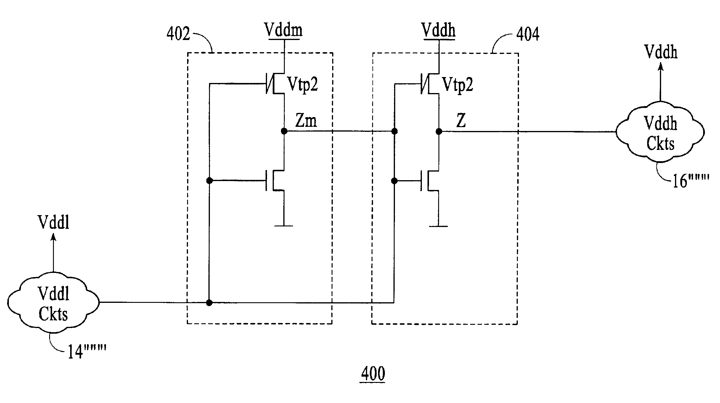
FIG. 5 is a level translation circuit 400 in accordance with the present invention. FIG. 5 illustrates the use of two stages of inverters 402 and 404 for level translation. The first stage includes an intermediate voltage power supply (Vddm).

If the reference voltage (Vddm) is Vddl+½(Vddh−Vddl), then a 2-stage level translator could be employed. This results in a |Vtp2| not needing to be so much higher than |Vtp1|. Also, since Vddm is derived from Vddh, Vddm will track Vddh and the issues associated with deactivation of Vddm while Vddh is active are resolved.

In co-pending U.S. patent application Ser. No. 10 / 439,362 (2750P) entitled “Level Translator Circuit for Power Supply Disablement,” filed on even date herewith and assigned to the assignee of the present application, Applicant has described other level translator circuits which address these problems. FIG. 6 is an embodiment of such a translator circuit 500. In this embodiment, a nfet transistor 502 is coupled to the gate of tran...

third embodiment

FIG. 8 is a level translation circuit 700 in accordance with the present invention. In this configuration, nfet transistor 426′ is now replaced with a higher threshold transistor 702. This will allow for a larger delta between Vddh and Vddl before leakage current in the active mode becomes of concern. This circuit behaves as follows. Node Y is held clamped at Vddh−Vtn; when Vddl is deactivated, Vddl=0 volts, then nfet transistor 702 is active and passes a ‘0’ value to node 1, thereby activating pfet transistor 308′″which results in node Z rising to Vddh which in turn causes pfet transistor 302′″ to be turned off. Nfet transistor 304′″ is also held off by Vddl being off. There is no leakage in this mode.

When Vddl is active and a high level is desired to be propagated, then there can be leakage consistent with that of FIG. 6 but now to a lesser degree or to a larger delta between Vddl and Vddh. In this case if Vddh−Vtn−Vtn2 is less than Vddl then no active state leakage will exist. Co...


PUM


Abstract

A level translator circuit for use between a transmitting voltage potential circuit and a receiving voltage potential circuit is disclosed. The translator circuit comprises a logic element coupled between the transmitting circuit and the receiving circuit for translating the voltage level. The logic element includes a device which has a threshold voltage of such a level that leakage current will be minimized when the transmitting voltage potential circuit's power supply is disabled. In one embodiment, the logic element comprises a multistage inverter wherein a first stage comprises an intermediate power supply. The intermediate power supply allows for the threshold voltage to be lower. Accordingly, a level translation circuit is provided that operates effectively even when one of the voltage potential circuits is turned off. In addition, leakage current is minimized for two distinct power supplies by providing a high threshold voltage device within the level translator of the circuit to ensure that an appropriate logical level is provided at the output of the circuit.

Description

CROSS-RELATED APLICATIONThe present application is related to application Ser. No. 10 / 439,362 entitled “Level Translator Circuit for Power Supply Disablement,” filed on even date herewith.FIELD OF THE INVENTIONThe present invention relates generally to a level translator circuit and more particularly to a level translator circuit for use between circuits having distinct power supplies wherein the lower voltage supply may be deactivated.BACKGROUND OF THE INVENTIONCircuits for voltage level translation are utilized in a variety of applications. Level translator circuits are employed to allow circuits operating at different power supply potentials to communicate with one another. Typically, the area, power and performance of the translator circuit are critical to the operations of each of the different circuits.FIG. 1 is a simple block diagram of a level translator system 10. The system 10 includes a level translator circuit 12 coupled between transmitting circuit 14 and downstream rec...

Claims


Application Information

Patent Timeline
Patent Type & Authority Patents(United States)
IPC IPC(8): H03K3/356H03K3/00
CPCH03K3/356113
Inventor CORREALE, JR., ANTHONY
Owner IMB
Why Eureka
Try Eureka