Inking unit for rotary printing machine

Inactive Publication Date: 2005-03-08
MANROLANAD AG
View PDF6 Cites 5 Cited by
  • Summary
  • Abstract
  • Description
  • Claims
  • Application Information

AI Technical Summary

Benefits of technology

It is an object of the invention to provide an inking unit with which an ink change is possible in subareas without having to empty the ink fountain entirely.
According to the invention, in the case of an inking unit of the generic type, the ductor can be pivoted into a second position while the ink fountain remains in the first position, thus providing a gap between the ductor and the ink fountain. By virtue of the ability of the ductor to be moved away from the ink fountain, which is pivoted away but not running empty, the possibility of changing its ink and cleaning it in subareas is provided without having to empty other subareas. It is therefore not necessary to design subareas of the ink fountain such that they can be pivoted separately, which is costly.

Problems solved by technology

It is therefore not necessary to design subareas of the ink fountain such that they can be pivoted separately, which is costly.

Method used


Image

  • Inking unit for rotary printing machine
  • Inking unit for rotary printing machine
  • Inking unit for rotary printing machine

Examples


Embodiment Construction

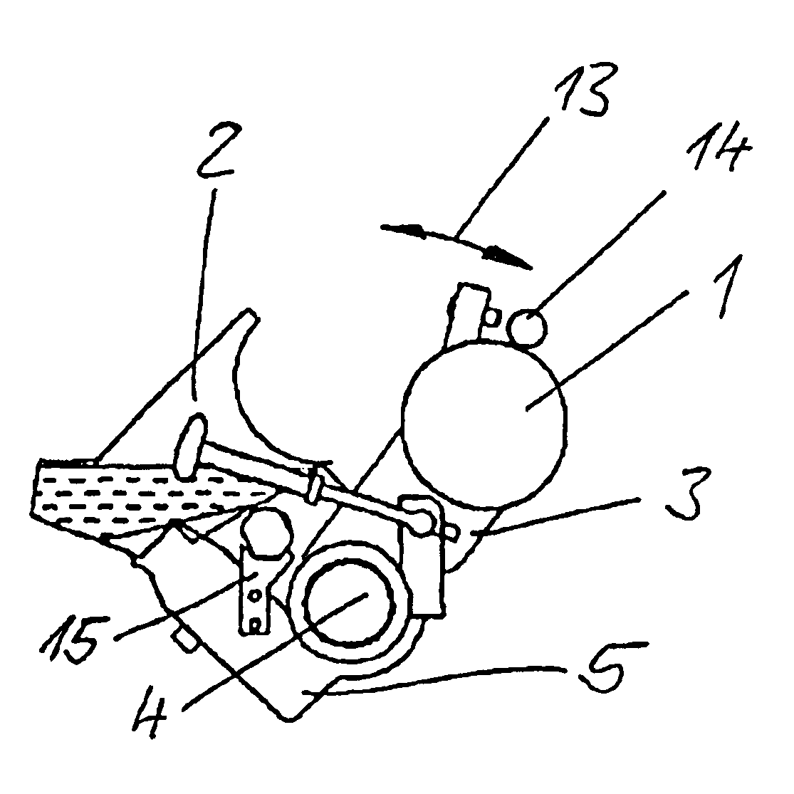
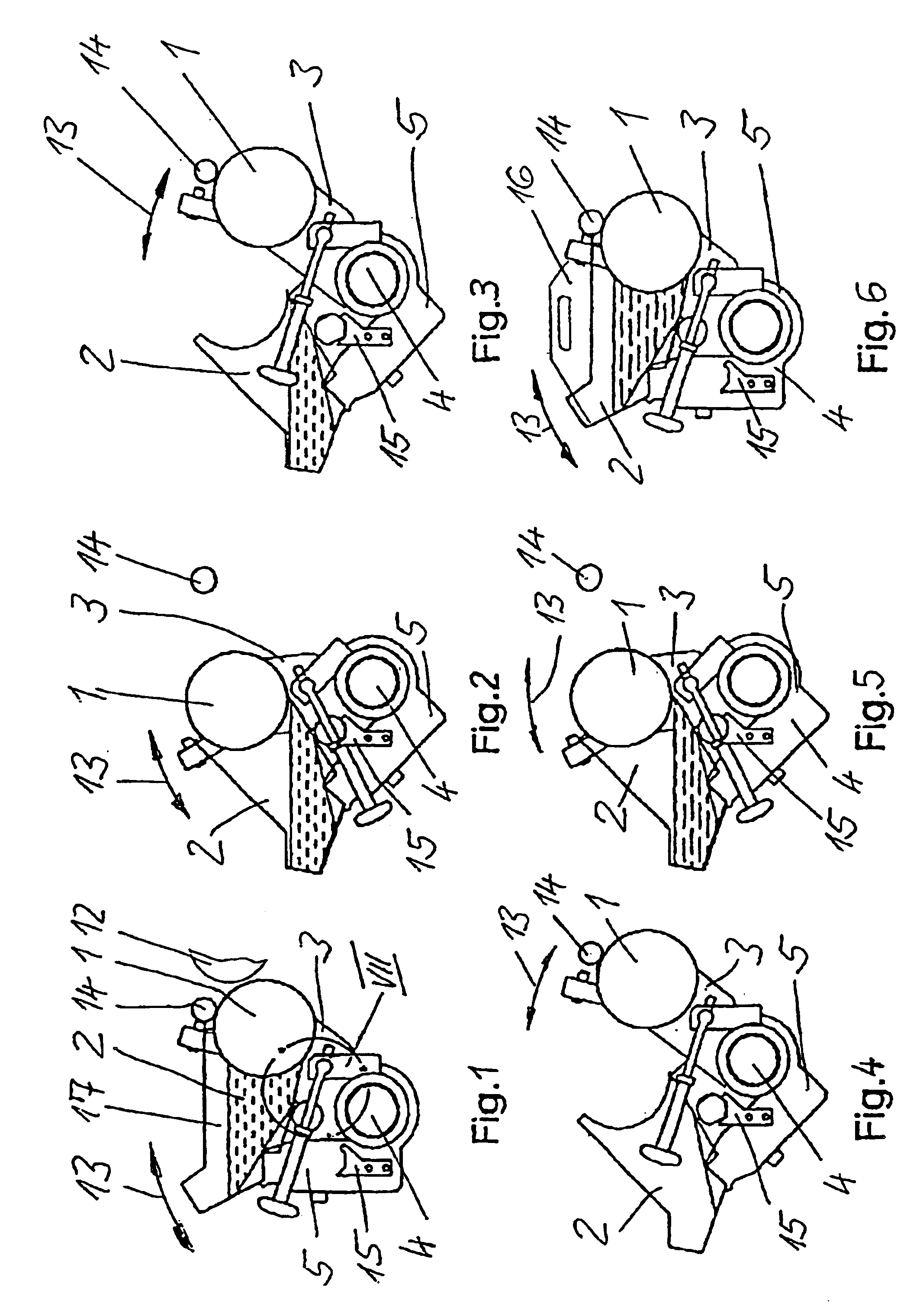
FIG. 1 shows a ductor 1 and an ink fountain 2 of an inking unit of a rotary printing machine. The ductor 1 is mounted in a ductor holder 3 and by means of the latter can be pivoted about a shaft 4. The ink fountain 2 is mounted on an ink fountain holder 5 and by means of the latter can be pivoted about the same shaft 4. The shaft 4 can also be connected permanently to the ductor holder 3 or to the ink fountain holder 5 and serve as a cross member for one of these holders 3, 5.

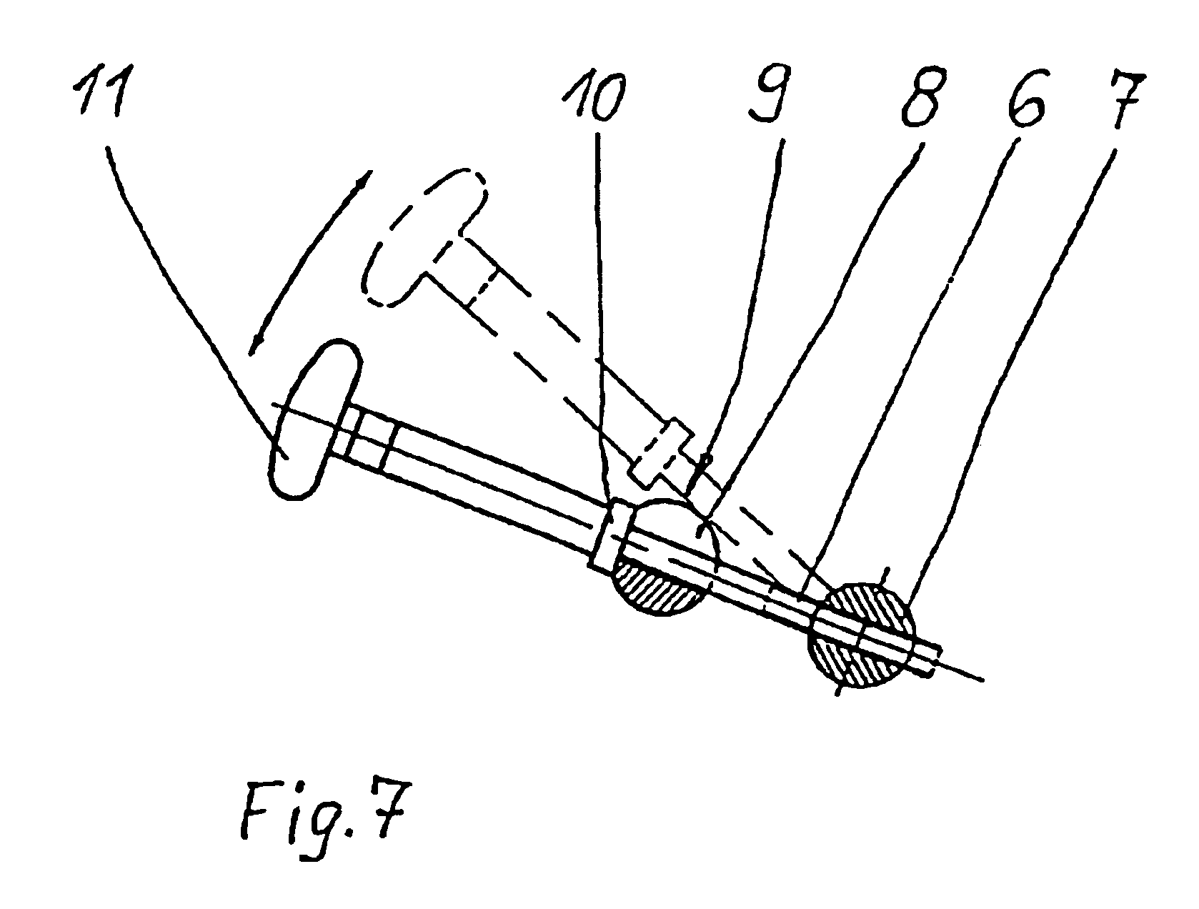
The ductor holder 3 and the ink fountain holder 5 are coupled by means of a coupling rod 6, so that they can be pivoted jointly about the shaft 4 (FIG. 7). The coupling rod 6 is firstly screwed into a spindle nut 7 rotatably mounted in the ductor holder 3 and secondly inserted into the slot 8 in a slotted bearing 9 fixed to the ink fountain holder 5. The ink fountain holder 5 rests with the slotted bearing 9 on an upset 10 of the coupling rod 6, under the action of gravity. As a result of rotation at the handle...


PUM


Abstract

An inking unit for a rotary printing machine includes an ink fountain, a pivotable ink fountain holder in which the ink fountain is mounted, an ink ductor, and a pivotable ink ductor holder in which the ink ductor is mounted. The ink ductor holder and the ink fountain holder are connected by an operating cylinder so that ductor and the ink fountain can be pivoted jointly to a first position in which ink flows out of the ductor without flowing out of the fountain, and so that the ductor can be pivoted away from the first position to a second position while the ink fountain remains in the first position, thereby creating a gap between the ductor and the ink fountain.

Description

BACKGROUND OF THE INVENTION1. Field of the InventionThe invention relates to an inking unit for a rotary printing machine, having a ductor which is pivotably mounted by means of a ductor holder, and an ink fountain which is pivotably mounted by means of an ink fountain holder, the ductor and the ink fountain being jointly pivotable to a first position in which the ink is moved away from the ductor without running out of the ink fountain.2. Description of the Related ArtU.S. Pat. No. 5,848,570 discloses an inking unit in which an ink ductor, together with an ink fountain, can be pivoted away from an operating position on a film roll. The ductor and also the ink fountain are each mounted in holders and can be pivoted with the latter. Ductor and ink fountain are first brought into a first pivoted position, in which the ink fountain can be emptied or an ink fountain insert can be removed. The ink fountain can then be brought on its own into a further pivoted position, the ink knife bein...

Claims


Application Information

Patent Timeline
Patent Type & Authority Patents(United States)
IPC IPC(8): B41F31/04
CPCB41F31/04
Inventor DYLLA, NORBERTKOPPELKAMM, GUNTERGEIGER, ULRICHHENNIG, BERND
Owner MANROLANAD AG
Why Eureka
Try Eureka