Foldable tire dolly

a dolly and tire technology, applied in the field of dolly, can solve the problems of difficult and time-consuming work, heavy and bulky devices, and difficulty in assembling, etc., and achieve the effect of convenient rolling

Inactive Publication Date: 2005-03-08
THE SEC OF THE ARMY
View PDF35 Cites 21 Cited by
  • Summary
  • Abstract
  • Description
  • Claims
  • Application Information

AI Technical Summary

Benefits of technology

The rectangular base member has a pair of adjustable wings, which are hinged to opposite ends of the rectangular base member. The hinges allow one of the wings to be positioned to form a ramp so that a tire can be easily rolled onto the rectangular base member and the wing raised to a supporting position where in combination with the wing on the opposite end of the rectangular base member the vehicle tire assembly will be held in a centered position on the base member. Adjustable positioning members are associated with the wings and rectangular base member with one end of the positioning member being attached to the base member and the other end attached to one of the wings. The positioning members can be adjusted so as to hold the wings in contact with the tire to keep the tire from excessive movement on the base member. The positioning memberes also intersect the angle between the associated wing and the base member to hold the tire in position on the dolly during movement of the dolly with the tire.

Problems solved by technology

When changing or rotating the tires the troops are required to lift and position the tires, which is a difficult and time-consuming job.
It is particularly difficult for the smaller members of the armed services who may lack both the strength and height necessary to position the large tires on an axle which is a substantial height above ground level.
Such devices are by nature heavy and bulky.
The combination of weight and storage space required by such structures makes them unsuitable for use in military units, which are deployed throughout the world.

Method used


Image

  • Foldable tire dolly
  • Foldable tire dolly
  • Foldable tire dolly

Examples


Embodiment Construction

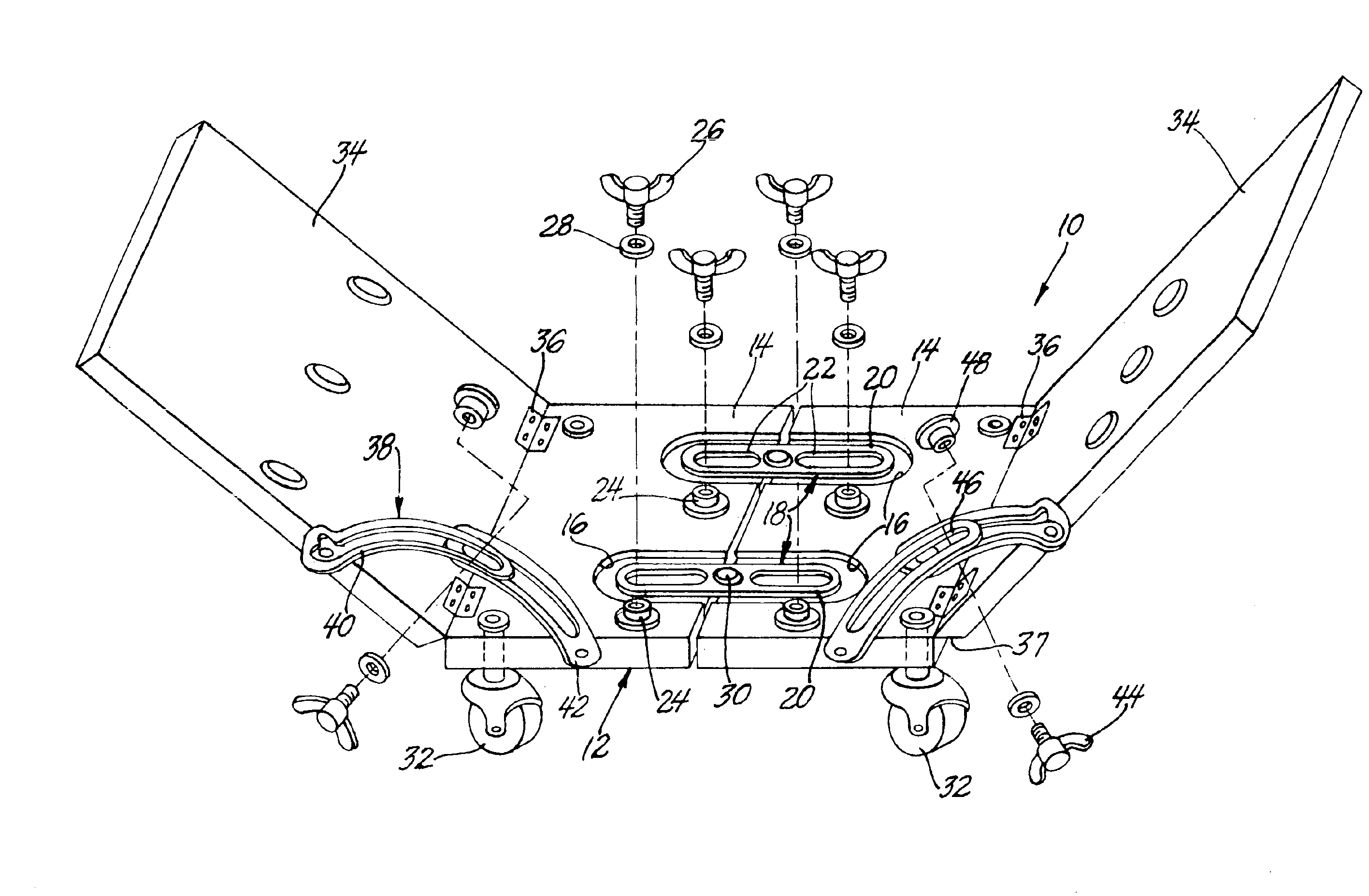
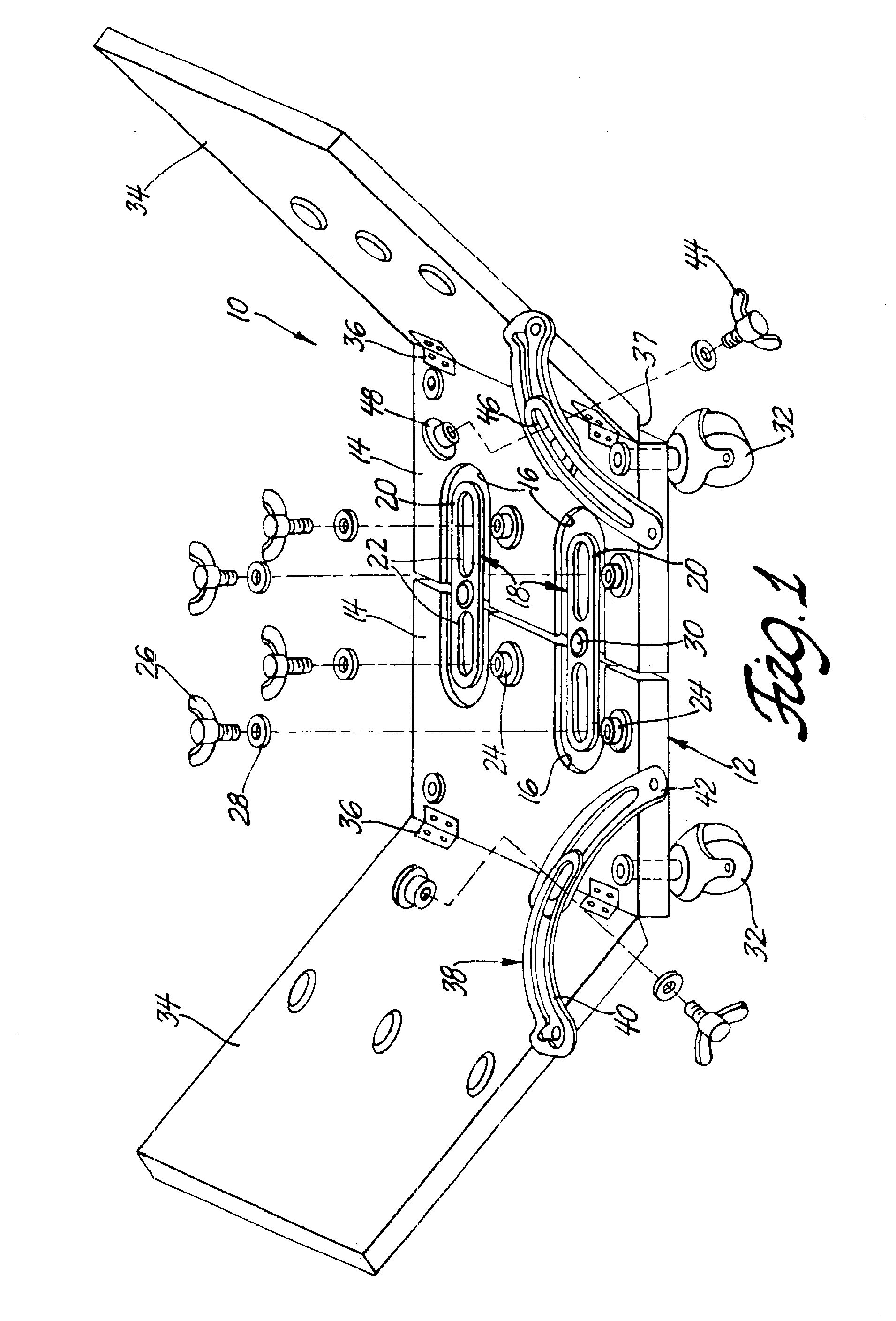
Referring to the accompanying drawing in which like numerals refer to like parts and initially to FIG. 1, a foldable tire dolly according to this invention is designated generally 10. The dolly has a rectangular base 12 composed or formed of two separate pieces 14 which abut each other near the centerline of the rectangular base 12. The two separate pieces 14 have two semi oval slots 16 incised into their upper surfaces so that when the pieces of the base member are brought into abutment there is an oval depression 18 formed in the upper surface of the rectangular base member 12. A complimentary oval shaped adjustable brace 20, sized slightly smaller than the oval depression 18, is nested in each of the oval depressions. Each of the oval braces 20 has two longitudinal oval apertures 22, one oval aperture being formed on each end of the individual oval brace. The longitudinal oval apertures 22 engage complementary internally threaded studs 24 located in and extending upward from the ...


PUM


Abstract

A foldable dolly for moving and positioning a vehicle tire assembly is formed with a rectangular base member mounted on a plurality of casters. Two wings are hinged to opposite ends of the rectangular member and have adjustable positioning members having one end attached to the base member and the other end attached to one of the wings. A plurality of bearings at least one bearing being mounted on each wing and one on the rectangular base member allow rotation of the tire assembly on the dolly and easy withdrawal of the dolly when the tire is mounted on a vehicle.

Description

BACKGROUND OF THE INVENTIONThis invention relates to dollies useful for the removal, moving and mounting of vehicle tires. More particularly, the dolly is useful in mounting and unmounting large vehicle tires from a vehicle.The military uses a variety of tactical ground vehicles, all of which use large truck tires. When changing or rotating the tires the troops are required to lift and position the tires, which is a difficult and time-consuming job. It is particularly difficult for the smaller members of the armed services who may lack both the strength and height necessary to position the large tires on an axle which is a substantial height above ground level. Wheeled dollies useful for removing or mounting vehicle wheels are known in the art. Generally such devices are constructed with a mainframe having upright standards and a second frame supported on the mainframe, which holds a tire assembly and is movable vertically on the upright standards to lift and position the tire. Such...

Claims


Application Information

Patent Timeline
Patent Type & Authority Patents(United States)
IPC IPC(8): B60B33/00B62B5/00B62B3/10
CPCB60B33/0002B60B33/0039B60B33/0049B62B3/104B62B5/0083B62B2206/04B62B2202/031B62B2203/60B62B2205/006
Inventor CHOPRA, KEWAL K.
Owner THE SEC OF THE ARMY
Why Eureka
Try Eureka