Display element, portable equipment and imaging device

a technology of portable equipment and display elements, which is applied in the direction of identification means, electrical apparatus casings/cabinets/drawers, instruments, etc., can solve the problems of difficult roll up of display elements, insufficient strength, and difficult to obtain operability, so as to achieve convenient rolling, high portability, and retention of flatness during periods of use.

Inactive Publication Date: 2010-07-22
FUJIFILM CORP
View PDF8 Cites 23 Cited by
  • Summary
  • Abstract
  • Description
  • Claims
  • Application Information

AI Technical Summary

Benefits of technology

[0011]An object of the present invention is to propose a flexible display element, portable equipment, and an imaging device which have high portability, ease of rolling, and retention of flatness during periods of use.

Problems solved by technology

As disclosed in Japanese Patent Application Laid-Open No. 2003-250074 and Japanese Patent Application Laid-Open No. 2003-274250, some kinds of portable equipment have flexible displays and have the following drawbacks: when the strength of a display is increased to keep the shape of the display pulled out of the main body of equipment, the strength becomes a resistance to rolling when the display is stored.
Thus it is difficult to roll up the display.
In order to keep the flatness, it is necessary to hold a gripping portion on the opposite side of the main body of equipment, thus operability is hard to obtain.
A small curvature causes an insufficient strength and the curvature has to be increased to obtain a sufficient strength.
As a result, a curved display may be viewed and the display may not have a designed aspect ratio.
Since the frames cannot be rolled up, a problem arises in storing the frames.
Thus such equipment is stored in a complicated manner and the size reduction is limited.
However, all of the methods are defective in ease of rolling (compactifying capability) and retention of flatness (operability) during periods of use.

Method used


Image

  • Display element, portable equipment and imaging device
  • Display element, portable equipment and imaging device
  • Display element, portable equipment and imaging device

Examples


first embodiment

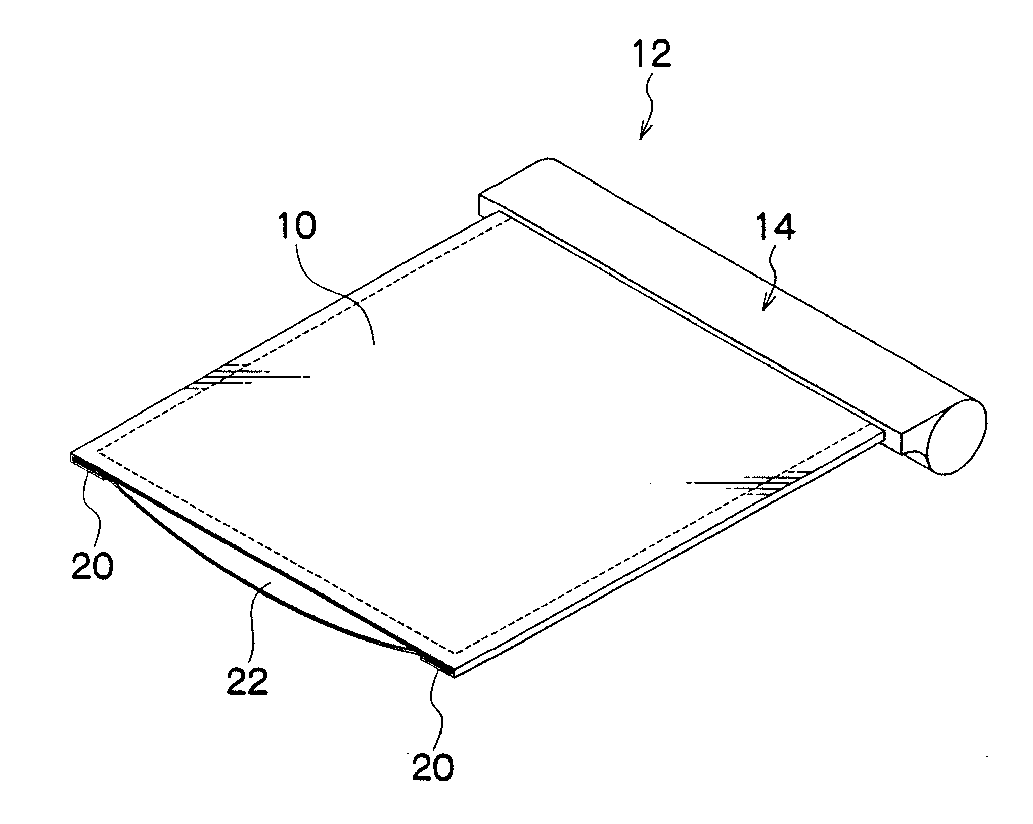
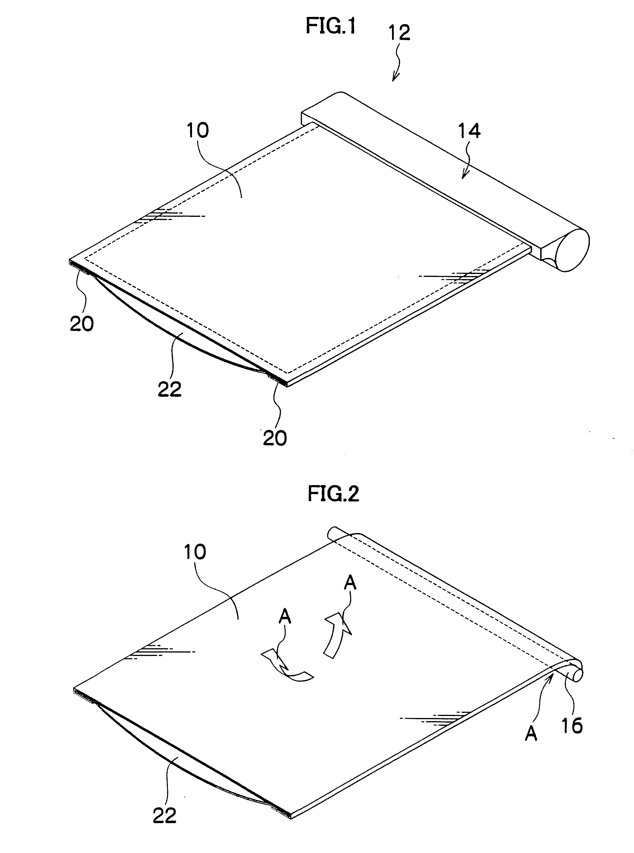
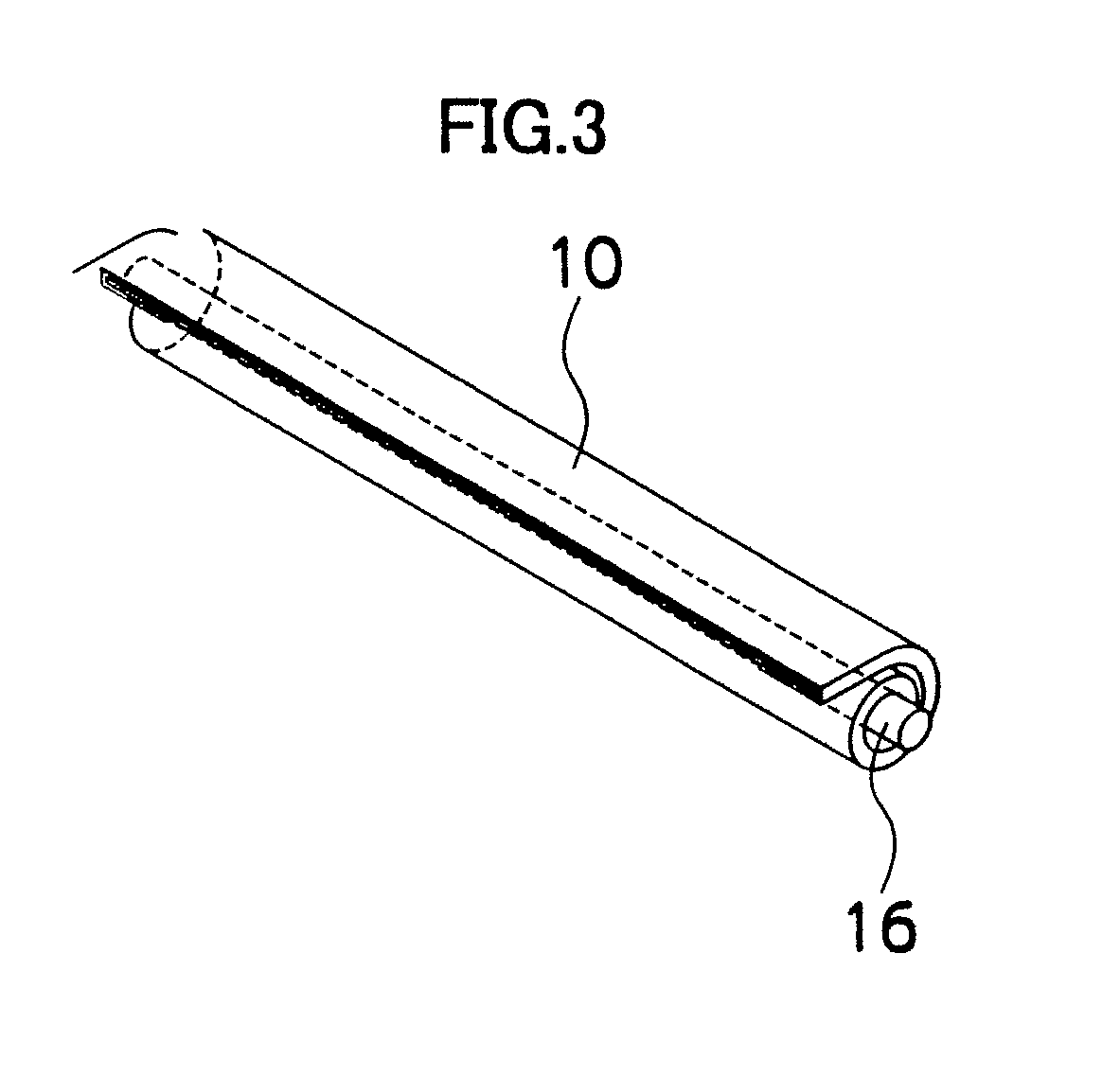
[0113]FIG. 1 is an outside drawing showing a display device (portable equipment) 12 including such a flexible display element 10 according to a In FIG. 1, the strip-like display element 10 is pulled out of a cylindrical main body 14. FIG. 2 shows the internal configuration of the main body 14 and a developed state of a roll-up shaft 16 for rolling up the display element 10 and the unrolled display element 10. FIG. 3 also shows the roll-up shaft 16 and the display element 10 having been completely rolled around the roll-up shaft 16.

[0114]As shown in FIG. 4, the main body 14 of FIG. 1 is made up of a cylindrical body 14A having open ends, and caps 14B for closing the open ends of the cylindrical body 14A. The roll-up shaft 16 is disposed between the caps 14B so as to rotate via a bearing portion 14C, and is urged in a rolling direction by a roll-up spring 18 (see FIG. 7). Further, the state of the unrolled display element10 is kept by a stopper (not shown).

[0115]As shown in FIG. 5A, ...

second embodiment

[0120]FIG. 8 is an outside drawing showing a display device (portable equipment) 112 including a flexible display element 110 according to a The FIG. 8 shows the state that the display element 110 is unrolled. FIG. 9 shows the single unit configuration of the display element 110. Over the opposite side of a display surface 110A, convex beam members 126 are bonded as shown in FIG. 11. With this configuration, the flexible display element 110 alone can be bent in direction D (and in the opposite direction) of FIG. 9 but cannot be bent in direction E (and in the opposite direction).

[0121]As shown in FIG. 12, a main body 114 is made up of a cylindrical body 114A having open ends, and caps 114B for closing the open ends of the cylindrical body 114A. A roll-up shaft 116 is disposed between the caps 114B so as to rotate via a bearing portion 114C and is urged in a rolling direction by a roll-up spring 118. Further, the state of the unrolled display element 110 is kept by a stopper (not sh...

third embodiment

[0127]FIG. 13A shows a display device 212 including a flexible display element 210 according to a FIG. 3 is a sectional view showing a back plate 222 combined with the display element 210. FIG. 13B is a sectional view showing the rolled display element 210. On the longitudinal ends of the back side of the display element 210, protruding pins 228 are disposed at a predetermined spacing along the longitudinal direction. Further, on the longitudinal ends of the back plate 222, long holes 230 are formed at the same spacing as the pins 228. The long holes 230 are formed along a direction (width direction) orthogonal to the longitudinal direction.

[0128]When the back plate 222 is attached to the display element 210 by fitting the pins 228 over the long holes 230, the long holes 230 press the pins 228 in the direction orthogonal to the longitudinal direction in the state of FIG. 13A where an external force is not applied to the back plate 222. Thus lateral pressures are applied to the disp...


PUM


Abstract

A portable equipment includes a flexible display element capable of being rolled up and unfurled, the display element including a back plate on a back side of the display element, which comes into contact with the display element when the display element is rolled up, and is bent such that at least a central portion of the back plate is separated from the display element due to a bend when the display element is unfurled, flatness of the display element being kept by a structure made up of the display element and the back plate when the display element is unfurled, and a pull-out slot for the display element on a main body of the portable equipment. The pull-out slot is flattened by a predetermined amount from a cross-sectional shape of the unrolled back plate, and has a clearance formed on a portion facing a surface of the display element.

Description

[0001]The present application is a Divisional application of U.S. patent application Ser. No. 12 / 002,753, filed on Dec. 19, 2007, and claims benefit of priority from Japanese Patent Application No. 2006-343267, filed on Dec. 20, 2006, the entire contents of which is incorporated herein by reference.BACKGROUND OF THE INVENTION[0002]1. Field of the Invention[0003]The present invention relates to a display element, portable equipment, and an imaging device which have high portability, a high compactifying capability, and high operability.[0004]2. Description of the Related Art[0005]Numerous kinds of portable equipment using flexible display elements which can be reduced in size when carried have been proposed. For example, like a roll-up display disclosed in Japanese Patent Application Laid-Open No. H09-216465, some kinds of portable equipment enable viewing of images recorded by thermal heads. According to Japanese Patent Application Laid-Open No. H09-216465, a recording medium pulled...

Claims


Application Information

Patent Timeline
Patent Type & Authority Applications(United States)
IPC IPC(8): G09G5/00
CPCG02F1/133305G02F1/133308G02F2001/133314G02F2201/54G09F9/35G09F11/02G09F9/301Y10S345/905G02F1/133314
Inventor MISAWA, ATSUSHI
Owner FUJIFILM CORP
Why Eureka
Try Eureka