
Mobile rehabilitative walker

Inactive Publication Date: 2005-08-30
HAWKES WADE
View PDF19 Cites 24 Cited by
  • Summary
  • Abstract
  • Description
  • Claims
  • Application Information

AI Technical Summary

Benefits of technology

[0010]It has been recognized that it would be advantageous to develop an apparatus to better orient a disabled, injured, or elderly user in an upright or standing orientation. It would also be advantageous to develop such an apparatus to facilitate the transition between an initial position, such as sitting in a wheelchair, to the upright, standing orientation. It would also be advantageous to develop such an apparatus for safely and securely maintaining the person in the upright, standing orientation. It would also be advantageous to develop such an apparatus more suitable for various different terrains, including irregular and / or rough surfaces. It would also be advantageous to develop such an apparatus that is more comfortable and supportive for the user. It would also be advantageous to develop such an apparatus for use with individuals of differing heights, and for use with a treadmill.
[0012]A plurality of wheels is rotatably coupled to the support frame to elevate the support frame above the support surface. The wheels are configured for multidirectional movement on the irregular and rough support surface. Advantageously, the wheels have a diameter sized to reduce friction between the wheels and the support surface, and are sized to easily roll over the irregular and rough surface.

Problems solved by technology

On the other hand, excessive unweighing, for example 80%, may render the exercise useless.
One disadvantage of such systems is that another person must be constantly available to “spot” the user.
In addition, such systems are confined to indoor facilities.
One disadvantage of such devices is that they are commonly configured to be utilized with hard, flat, and smooth surfaces.
In addition, such devices are often difficult to utilize with wheelchairs.
The user is subjected to increased risk of injury during the transition, and typically requires a great deal of assistance.
Another disadvantage with typical walkers is that they are not suitable for use on a treadmill.

Method used


Image

  • Mobile rehabilitative walker
  • Mobile rehabilitative walker
  • Mobile rehabilitative walker

Examples


Embodiment Construction

[0026]Reference will now be made to the exemplary embodiments illustrated in the drawings, and specific language will be used herein to describe the same. It will nevertheless be understood that no limitation of the scope of the invention is thereby intended. Alterations and further modifications of the inventive features illustrated herein, and additional applications of the principles of the inventions as illustrated herein, which would occur to one skilled in the relevant art and having possession of this disclosure, are to be considered within the scope of the invention.

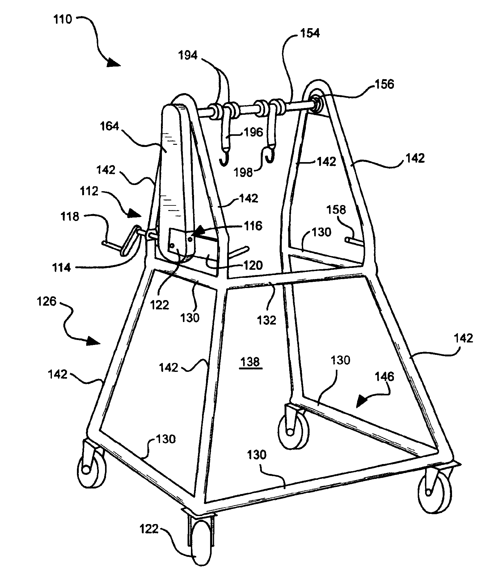
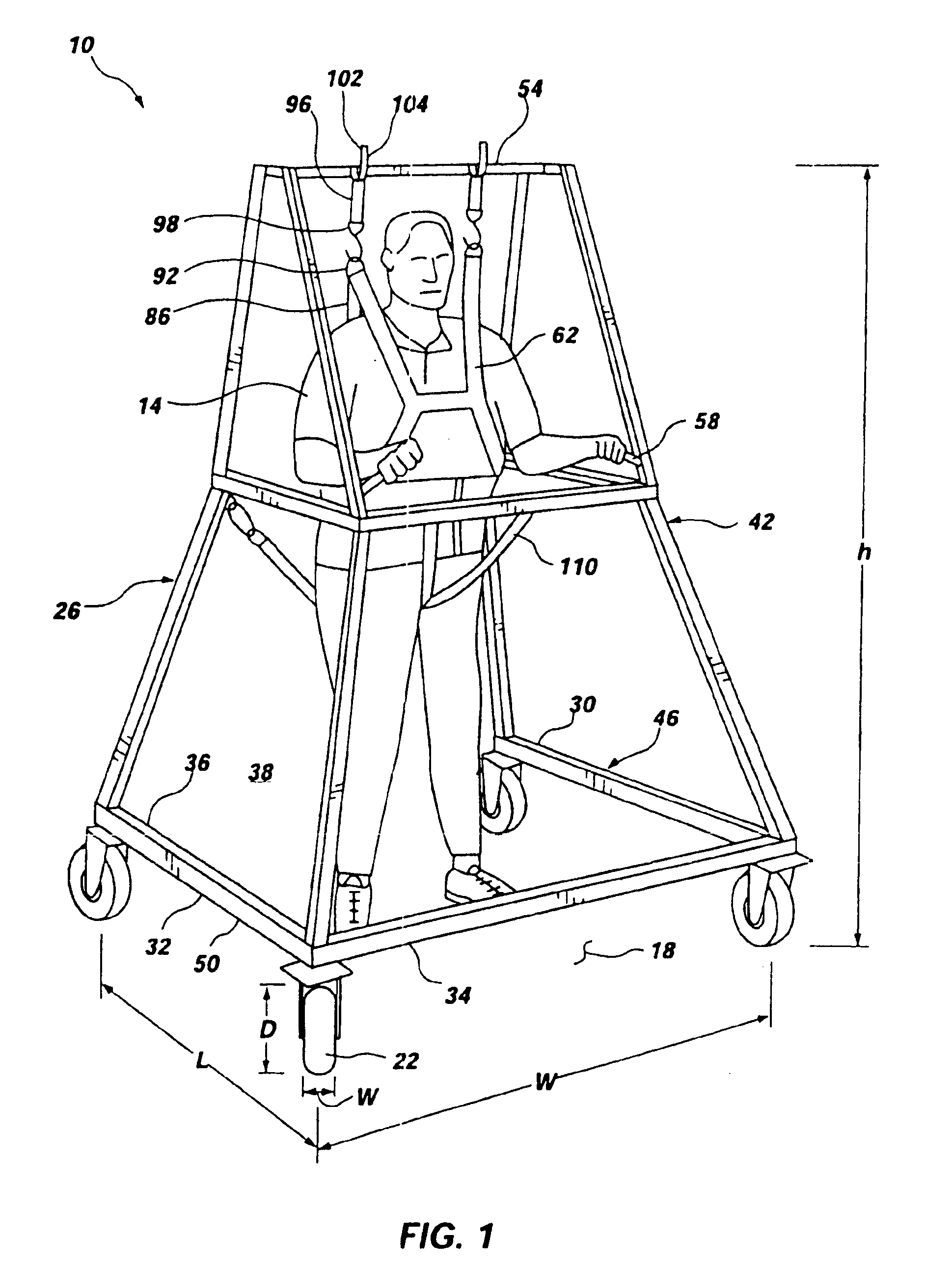
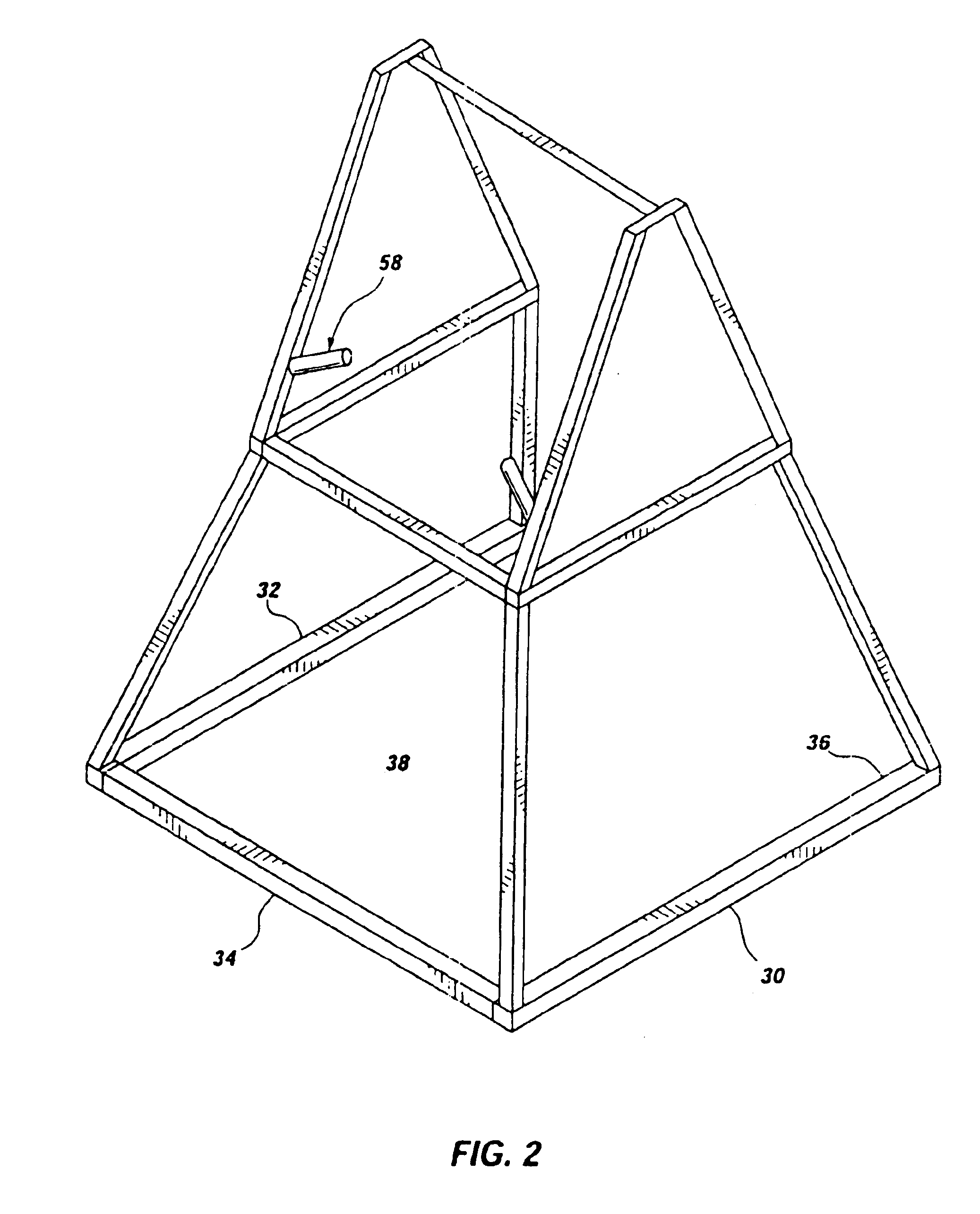
[0027]As illustrated in FIGS. 1 and 2, a mobile rehabilitative walker, indicated generally at 10, in accordance with the present invention is shown for orienting and supporting a person 14 in an upright orientation. As indicated above, the person may be disabled, such as a quadriplegic or paraplegic person or user; have an injury, such as a pulled tendon in the leg; may be elderly; or have any other condition whi...


PUM


Abstract

A mobile, rehabilitative walker is configured for use outdoors on an irregular or rough support surface. The walker includes a support frame, configured for supporting a person in an upright position, having a plurality of frame members defining an open rear end and an interior space sized for receiving a wheelchair. A plurality of wheels are rotatably coupled to the support frame, and configured for multidirectional movement on the support surface. A support harness is vertically suspended from a rotatable upper rail of the support frame. A crank mechanism is coupled to the upper rail, and configured to rotate the upper rail to draw the support harness upward. The crank mechanism includes a crank handle located near the rear end of the support frame to facilitate rotation of the upper rail.

Description

[0001]This application is a continuation-in-part of U.S. patent application Ser. No. 09 / 378,388, filed on Aug. 20, 1999 now U.S. Pat. No. 6,578,594.BACKGROUND OF THE INVENTION[0002]1. Field of the Invention[0003]The present invention relates generally to rehabilitative walkers for general mobility and / or rehabilitation treatment of injured or disabled persons. More particularly, the present invention relates to a mobile rehabilitative walker that allows mobility on irregular surfaces, and facilitates transition of the user from a sitting position to an upright position.[0004]2. Related Art[0005]It is often necessary or desirable for individuals with disabilities or injuries to be oriented in an upright or standing orientation for purposes of exercise and / or variety. For example, persons with a leg injury may need to stand and walk to exercise the injury as part of a rehabilitation procedure. As another example, elderly persons or quadriplegic and paraplegic persons must exercise and...

Claims


Application Information

Patent Timeline
IPC IPC(8): A61H3/00
CPCA61H3/008A61H3/04A61H2003/007A61H2201/1633A61H2201/0192A61H2201/1616A61H2201/1621A61H2201/163A61H2201/1635A61H2201/1652
Inventor HAWKES, WADEMCKENZIE, KYLEBOWEN, BRUCE G.
Owner HAWKES WADE
Learn More