Fluid pump relief valve

a technology of pump and valve body, which is applied in the direction of pump parameter, positive displacement liquid engine, liquid fuel engine, etc., can solve the problems of undesirable impede the flow of fluid through the pump and failure of the pump

Inactive Publication Date: 2005-03-08
STANDEX INT CORP
View PDF29 Cites 10 Cited by
  • Summary
  • Abstract
  • Description
  • Claims
  • Application Information

AI Technical Summary

Benefits of technology

In accordance with a further aspect of the invention, the relief valve cavity includes a barrier to prevent overtravel of the poppet by engaging the poppet when the poppet moves a maximum allowed distance. Additionally, a force adjustment device may be employed to vary the force of the flow tube actuator.

Problems solved by technology

However, the usual manner of positioning the pressure relief valve in the pump can undesirably impede the flow of fluid through the pump.
Additionally, the pressure relief valves are often configured in a way that promotes failure of the pump in the event of a failure of the relief valve.

Method used


Image

  • Fluid pump relief valve
  • Fluid pump relief valve
  • Fluid pump relief valve

Examples


Embodiment Construction

)

Preferred embodiments of the present invention will now be described with reference to the accompanying drawings, wherein like reference characters designate like or similar parts throughout. The terminology used herein is intended to be interpreted in its broadest reasonable manner, even though it is being utilized in conjunction with a detailed description of certain specific preferred embodiments of the present invention. This is further emphasized below with respect to some particular terms used herein. Any terminology intended to be interpreted by the reader in any restricted manner will be overtly and specifically defined as such in this specification.

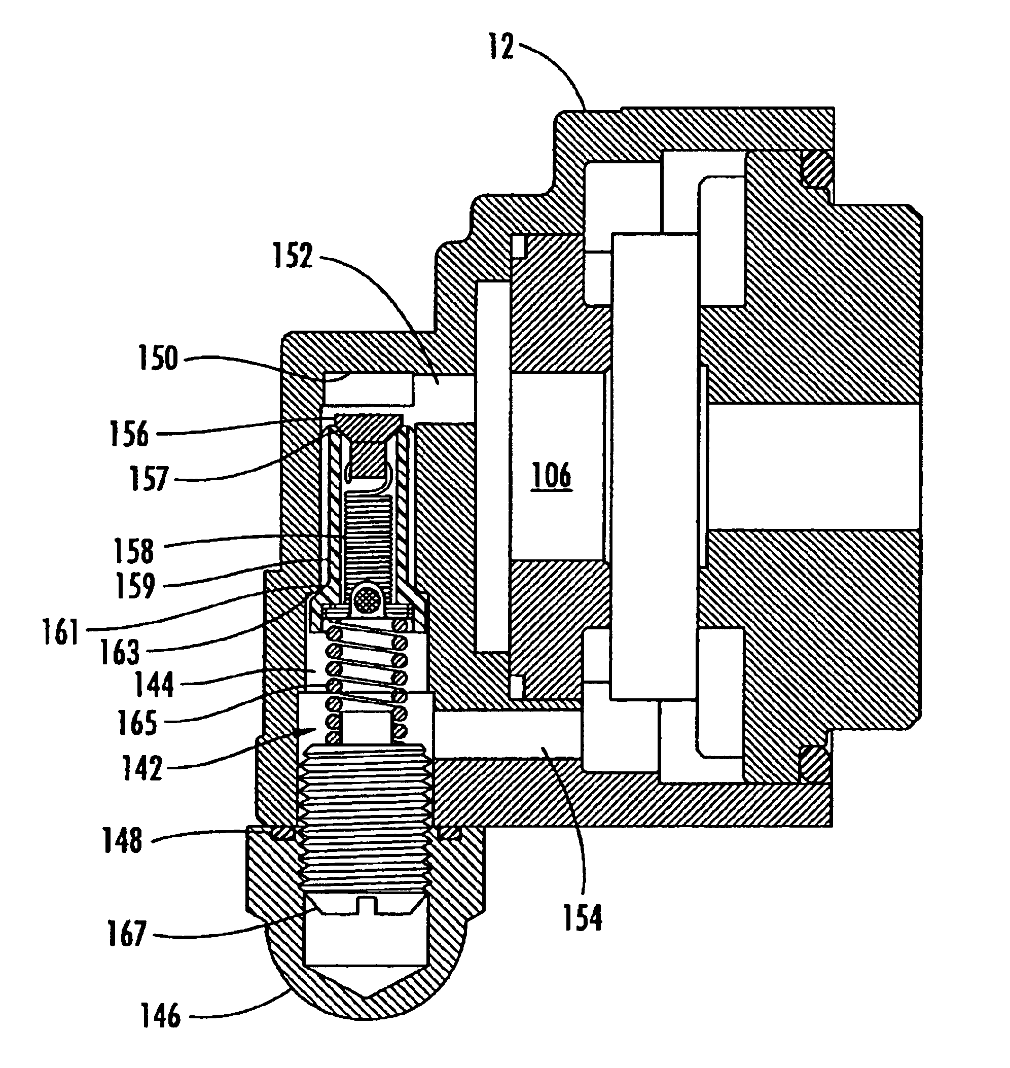
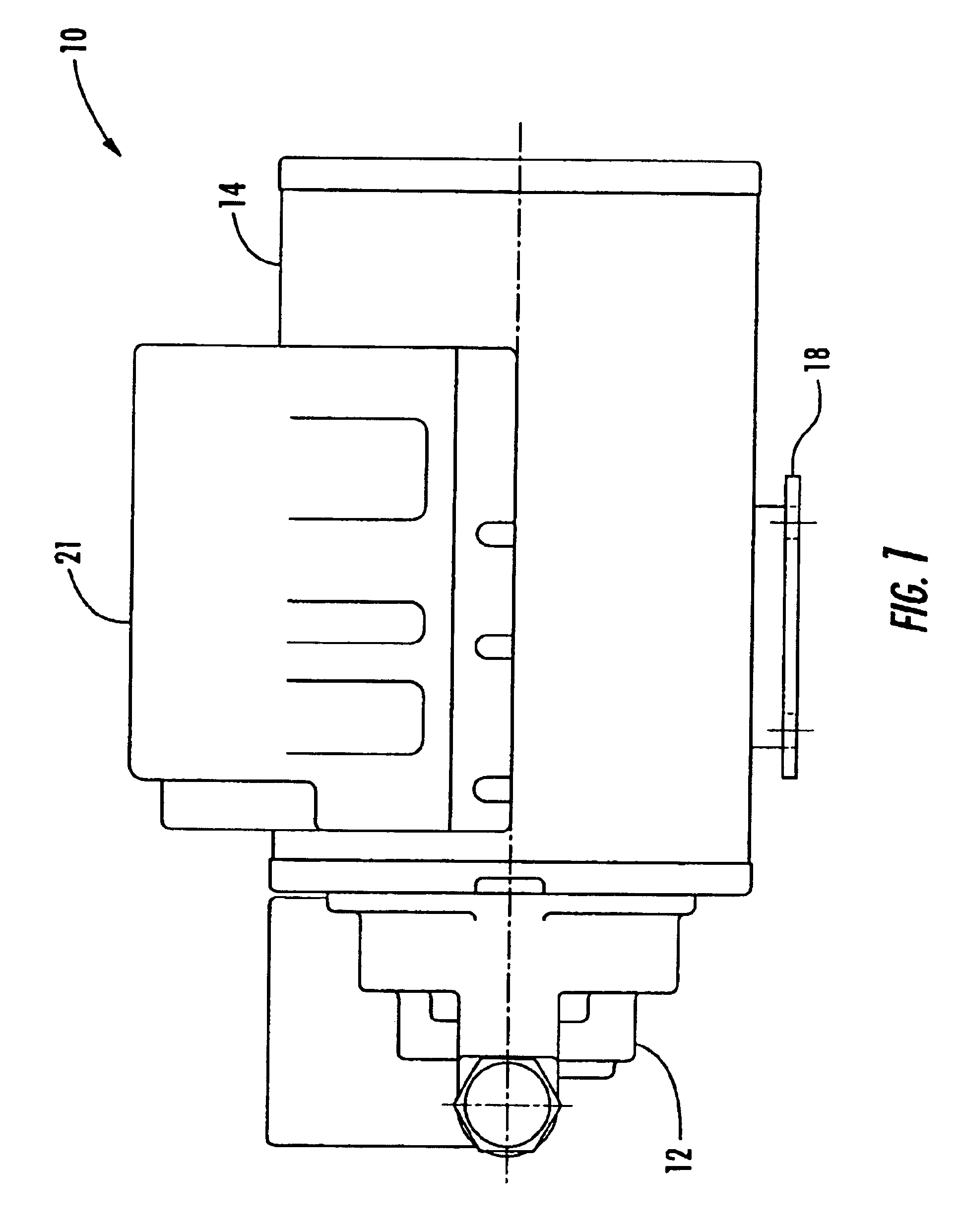
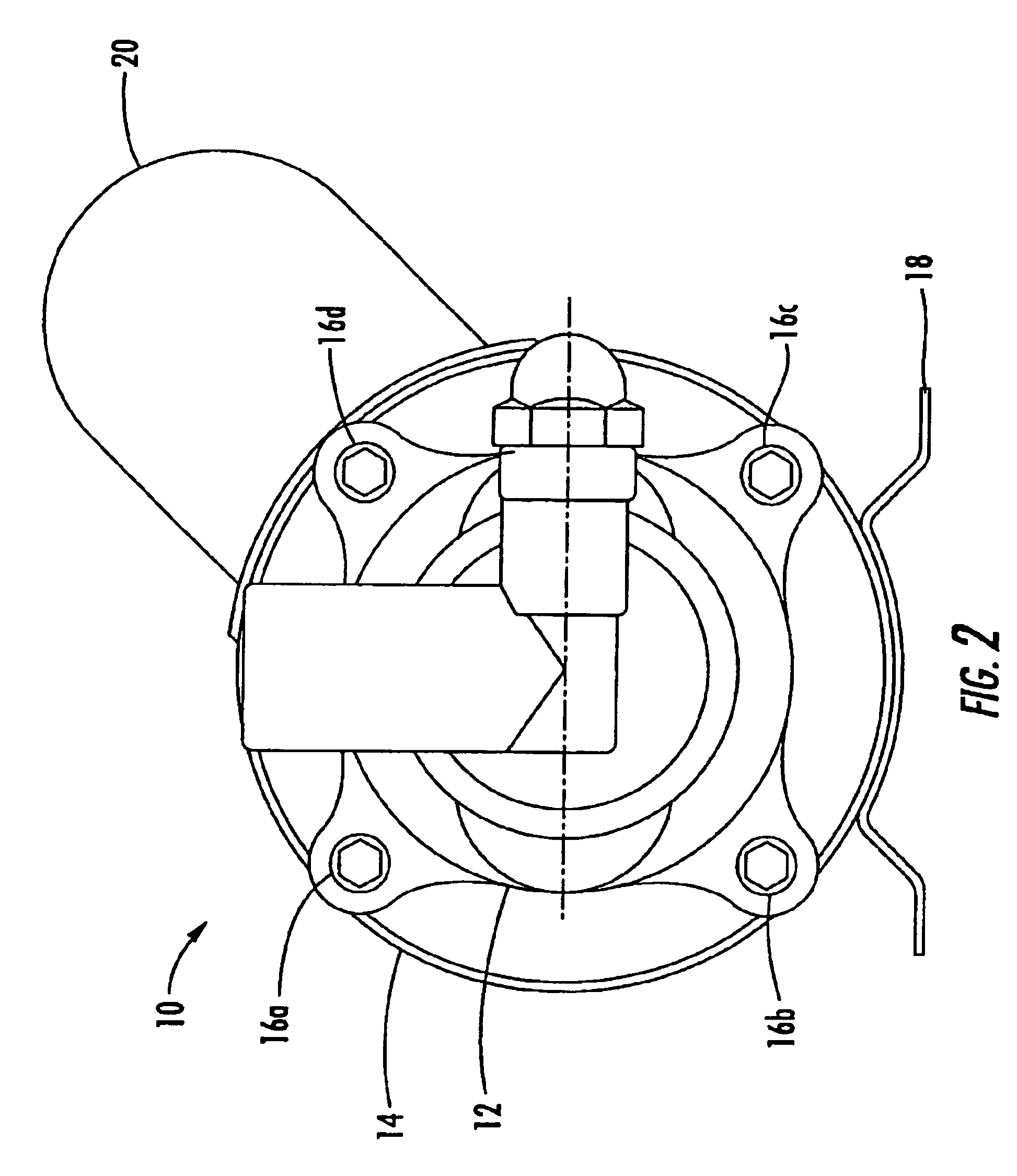
FIGS. 1 and 2 illustrate, respectively, side and end views of a canned motor pump 10 according to a preferred embodiment of the invention. The pump 10 includes a pump head housing 12 which houses internal components of the pump attached to a motor housing 14 for housing electric motor components. The pump head housing 12, which ...


PUM


Abstract

A pump head for a fluid pump driven by a motor includes an inlet for receiving fluid at a first pressure and an outlet for outputting fluid at a second pressure greater than the first pressure. A relief valve cavity formed in the pump head housing includes a first portion in fluid communication with the inlet and a second portion in fluid communication with the outlet. A relief valve is disposed in the relief valve cavity with no portion of the relief positioned to block or otherwise impede the normal flow of fluid through the inlet or outlet. The relief valve is bi-directional and configured to operate in two modes including: (1) a low pressure relief mode where fluid flows from the inlet to the outlet when fluid pressure at the inlet exceeds fluid pressure at the outlet by a first threshold amount; and (2) a high pressure relief mode where fluid flows from the outlet to the inlet when fluid pressure at the outlet exceeds fluid pressure at the inlet by a second threshold amount greater than the first threshold amount. The relief valve cavity is specially configured to provide a barrier preventing an element of the relief valve from damaging the pump head in the event the relief valve element fails.

Description

FIELD OF THE INVENTIONThe present invention relates generally to fluid pumps. More particularly, the present invention relates to a motor driven fluid pump having a bi-directional relief valve with the relief valve advantageously positioned in the pump head housing.BACKGROUND OF THE INVENTIONFluid pumps with integral motors, such as so-called “canned” pumps, are generally employed in a variety of applications. For example, fluid motor pumps are often used to move potable fluids, such as water, in beverage dispensing machines. To prevent overpressure conditions, fluid pumps typically employ a pressure relief valve positioned in or near the low pressure inlet. However, the usual manner of positioning the pressure relief valve in the pump can undesirably impede the flow of fluid through the pump. Additionally, the pressure relief valves are often configured in a way that promotes failure of the pump in the event of a failure of the relief valve.What is needed, therefore, is a fluid pum...

Claims


Application Information

Patent Timeline
Patent Type & Authority Patents(United States)
IPC IPC(8): F04C11/00F04D13/06F04D29/08F04D29/58F04D29/10H02K5/12H02K5/128F04C2/344F04C2/00F04C14/06F04C14/26F04C14/28F04C28/24
CPCF04C11/008F04C14/06F04C14/26F04D13/0633F04C28/24F04D29/106F04D29/588H02K5/128F04C14/28F04B2201/0801F04B2203/0205F04C2/3446F04C2270/18F04C2270/19
Inventor KIMBERLIN, ROBERT R.HARVEY, III, ROBERT E.
Owner STANDEX INT CORP
Why Eureka
Try Eureka