Structures and methods for creating cavities in interior body regions

a technology of interior body and cavity, applied in the field of structures and procedures, can solve the problems of overall adverse impact on the quality of life and chronic complications

Inactive Publication Date: 2005-03-08
ORTHOPHOENIX
View PDF40 Cites 402 Cited by
  • Summary
  • Abstract
  • Description
  • Claims
  • Application Information

AI Technical Summary

Problems solved by technology

These conditions, if not successfully treated, can result in deformities, chronic complications, and an overall adverse impact upon the quality of life.

Method used


Image

  • Structures and methods for creating cavities in interior body regions
  • Structures and methods for creating cavities in interior body regions
  • Structures and methods for creating cavities in interior body regions

Examples


Embodiment Construction

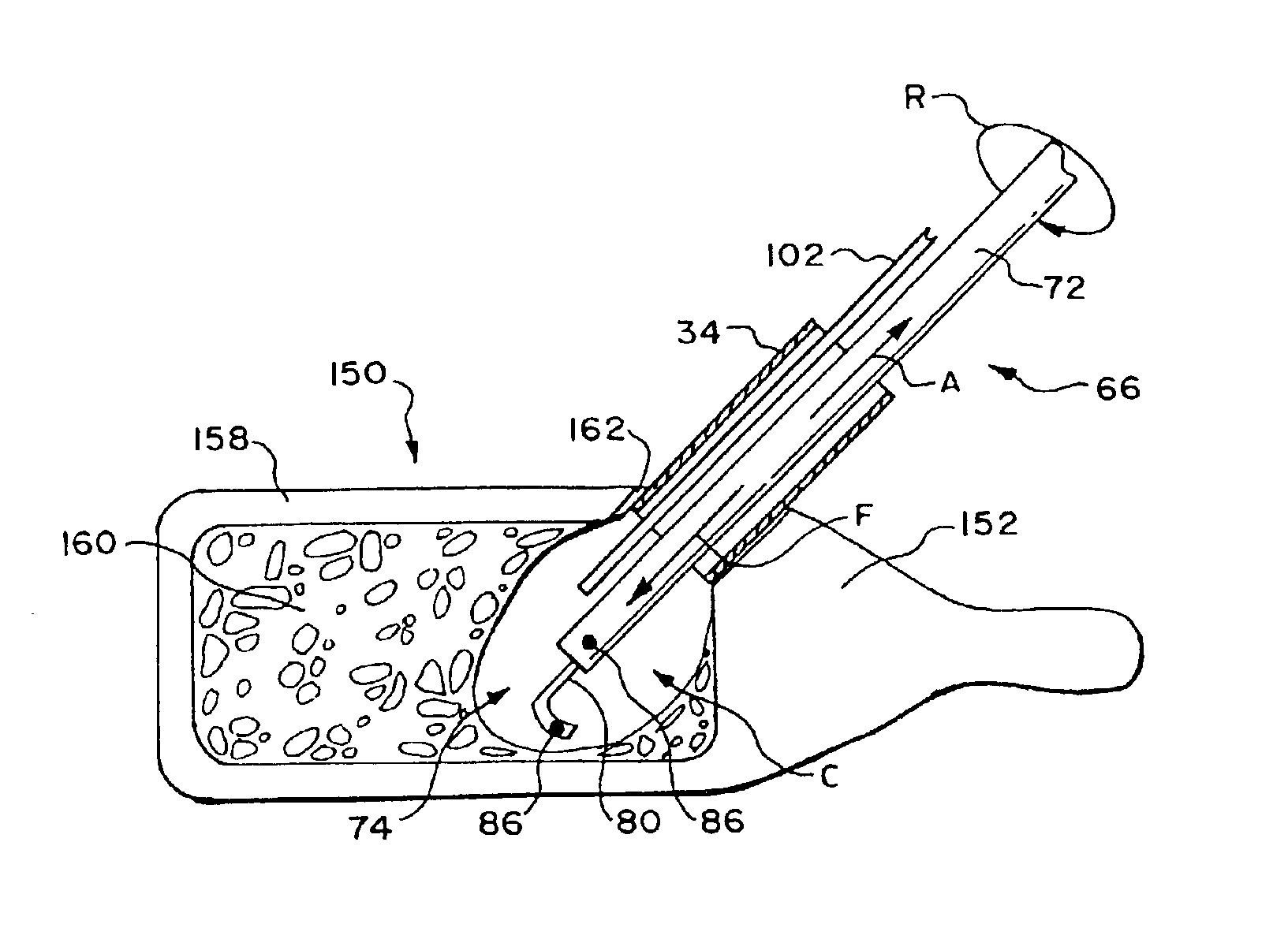
The systems and methods embodying the invention can be adapted for use virtually in any interior body region, where the formation of a cavity within tissue is required for a therapeutic or diagnostic purpose. The preferred embodiments show the invention in association with systems and methods used to treat bones. This is because the systems and methods which embody the invention are well suited for use in this environment. It should be appreciated that the systems and methods which embody features of the invention can be used in other interior body regions, as well.

I. Rotatable Cavity Forming Structures

A. Rotatable Loop Structure

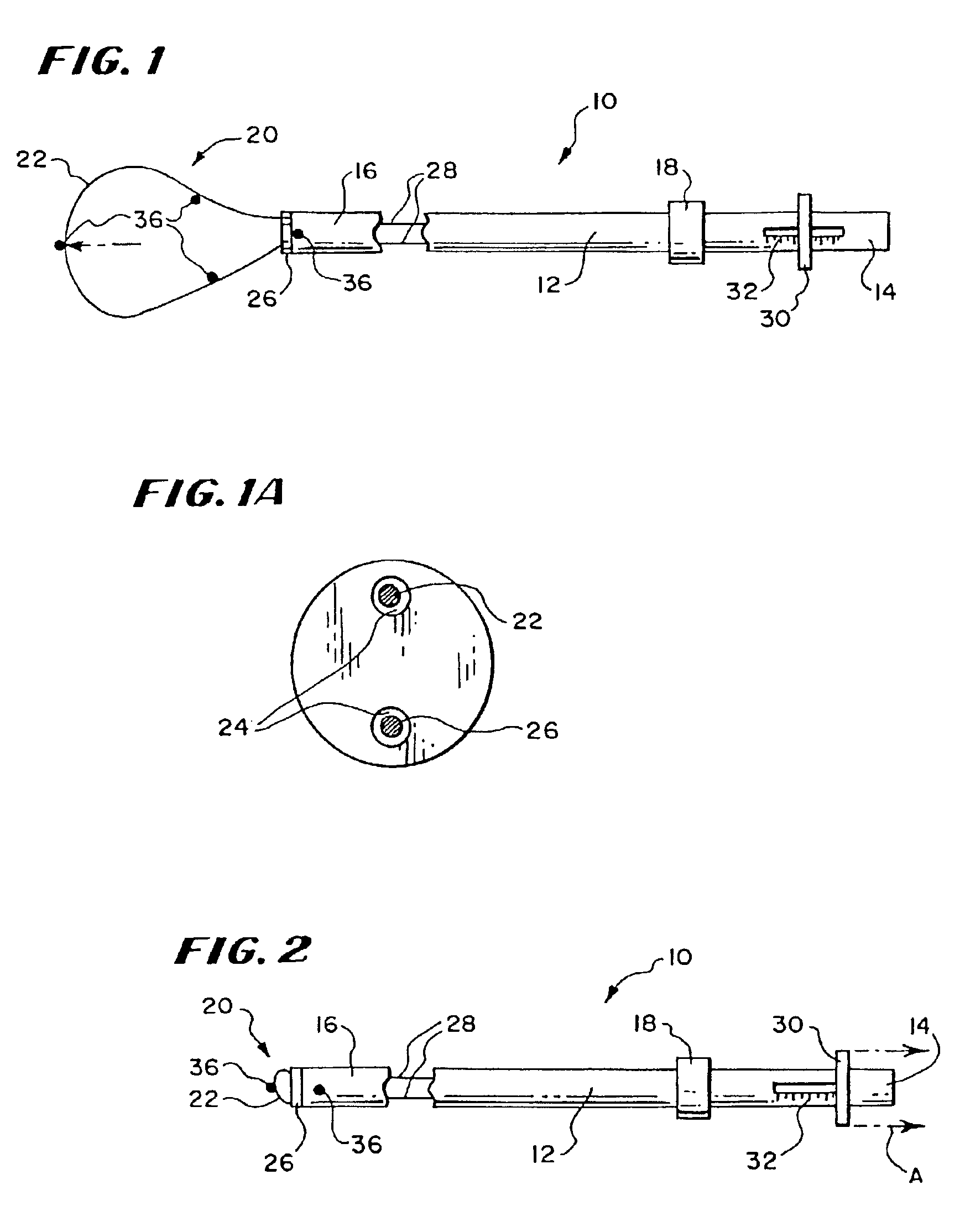
FIG. 1 shows a rotatable tool 10 capable of forming a cavity in a targeted treatment area. The tool 10 comprises a catheter tube 12 having a proximal and a distal end, respectively 14 and 16. The catheter tube 12 preferable includes a handle 18 to aid in gripping and maneuvering the tube 12. The handle 18 can be made of a foam material secured about the cath...


PUM

PropertyMeasurementUnit
structuresaaaaaaaaaa
movementaaaaaaaaaa
flexibleaaaaaaaaaa

Abstract

Tools carry structures that are deployed inside bone and, when manipulated, cut cancellous bone to form a cavity.

Description

FIELD OF THE INVENTIONThe invention relates to structures and procedures, which, in use, form cavities in interior body regions of humans and other animals for diagnostic or therapeutic purposes.BACKGROUND OF THE INVENTIONCertain diagnostic or therapeutic procedures require the formation of a cavity in an interior body region.For example, as disclosed in U.S. Pat. Nos. 4,969,888 and 5,108,404, an expandable body is deployed to form a cavity in cancellous bone tissue, as part of a therapeutic procedure that fixes fractures or other abnormal bone conditions, both osteoporotic and non-osteoporotic in origin. The expandable body compresses the cancellous bone to form an interior cavity. The cavity receives a filling material, which provides renewed interior structural support for cortical bone.This procedure can be used to treat cortical bone, which due to osteoporosis, avascular necrosis, cancer, or trauma, is fractured or is prone to compression fracture or collapse. These conditions,...

Claims


Application Information

Patent Timeline
Patent Type & Authority Patents(United States)
IPC IPC(8): A61B17/32A61B17/16A61B17/88A61B19/02A61B19/00A61F2/44A61F2/46A61B17/22A61B18/20A61B18/24A61F2/30A61B17/00A61B17/02A61M1/00A61B18/00
CPCA61B17/1671A61B17/22012A61B17/320016A61B17/32056A61B17/320758A61B19/026A61F2/441A61F2/4601A61B17/164A61B17/1617A61F2210/0085A61B17/1644A61B17/8805A61B18/24A61B2017/00261A61B2017/22014A61B2017/320008A61B2017/320733A61B2217/005A61B2217/007A61F2/44A61F2/4611A61F2002/30583A61F2002/30677A61B50/30
Inventor REILEY, MARK ASCHOLTEN, ARIE
Owner ORTHOPHOENIX
Why Eureka
Try Eureka