Circuit breaker with delay mechanism

a delay mechanism and circuit breaker technology, applied in the field of circuit breakers, can solve problems such as supplying a time delay to the switch operated by the inertia member

Inactive Publication Date: 2005-03-08
EATON CORP
View PDF11 Cites 30 Cited by
  • Summary
  • Abstract
  • Description
  • Claims
  • Application Information

AI Technical Summary

Benefits of technology

Another aspect of the present invention is to provide an improved circuit breaker having an inertial delay mechanism that avoids the use of a relatively massive inertial member by providing a relatively small inertial member and a pair of springs that interact with different structures of the circuit breaker.

Problems solved by technology

After the lay shaft passes through the intermediate position on its way to the second position, the first spring overcomes any bias of the second spring and begins to rotate the inertia member toward the terminal position, thereby providing a time delay to a switch operated by the inertia member.

Method used


Image

  • Circuit breaker with delay mechanism
  • Circuit breaker with delay mechanism
  • Circuit breaker with delay mechanism

Examples


Embodiment Construction

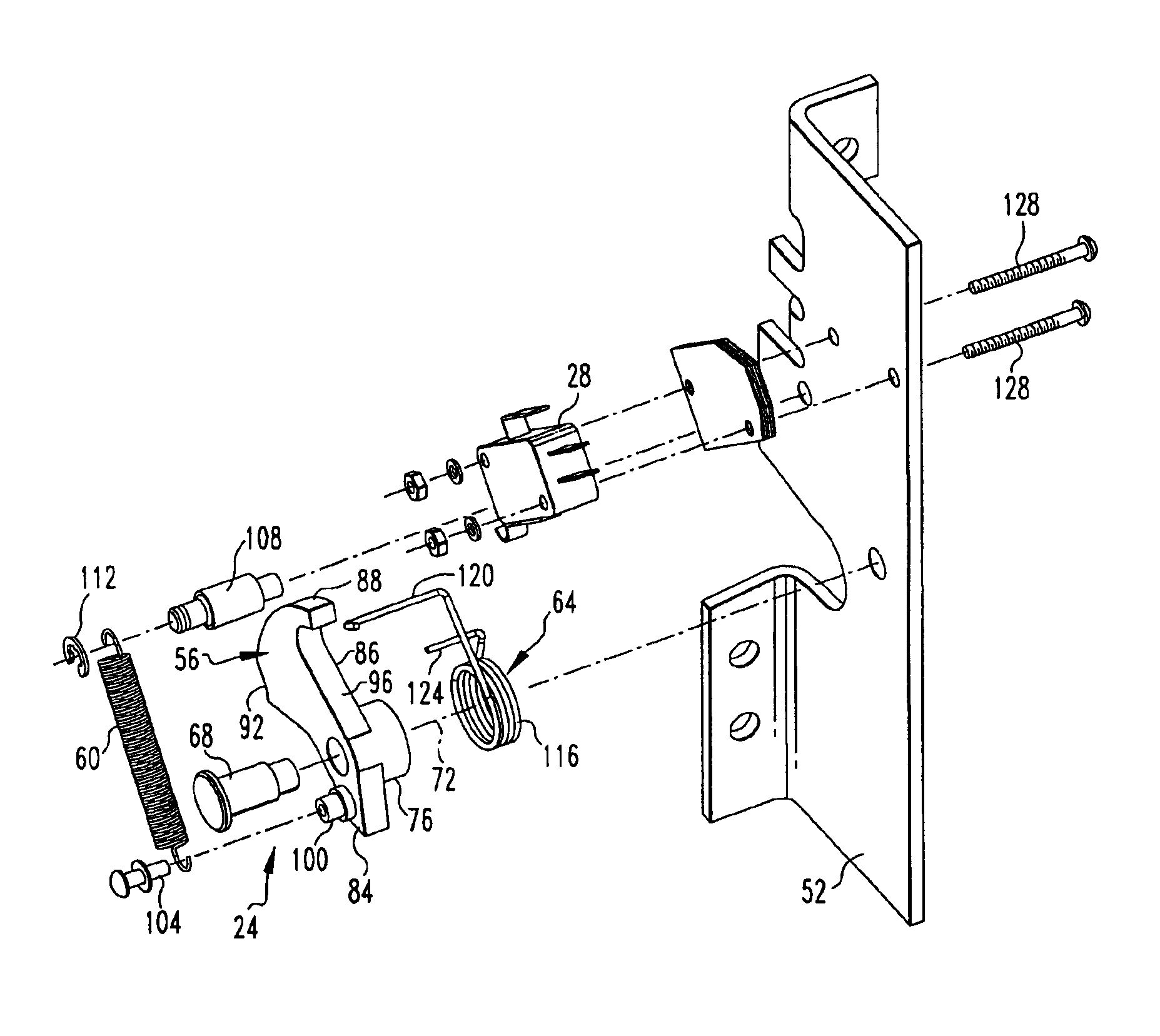
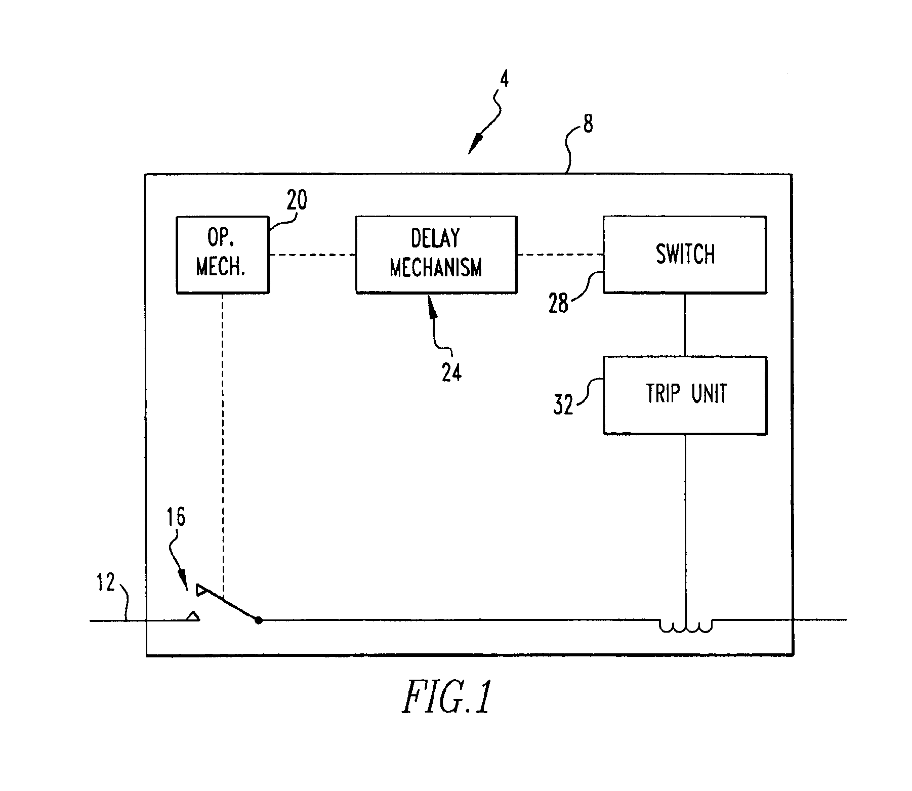
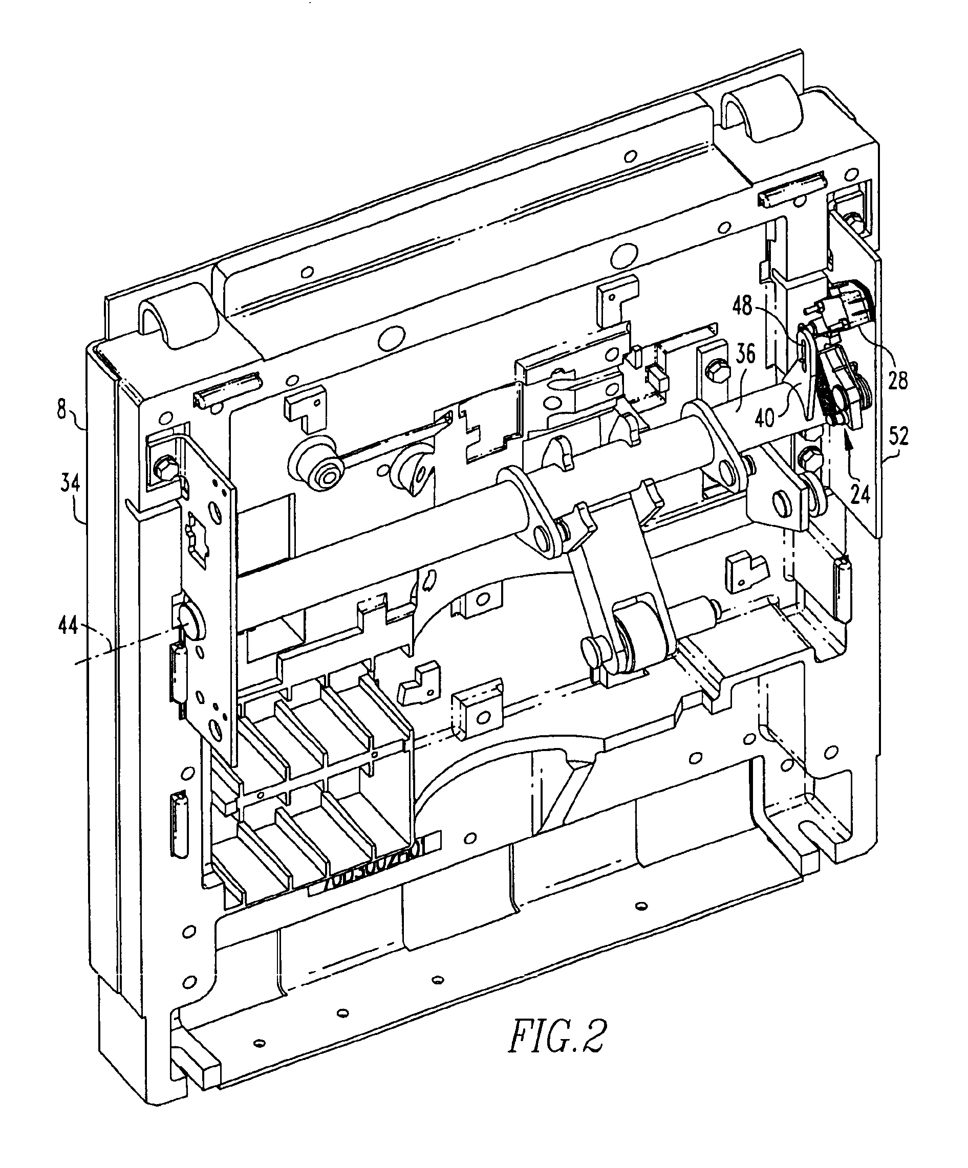
An improved circuit breaker 4 in accordance with the present invention is indicated schematically FIG. 1. The circuit breaker 4 includes a housing 8 that carries a conductor 12 which passes current through the circuit breaker 4, a set of separable contacts 16 interposed within the conductor 12 to selectively interrupt the flow of current therethrough, and an operating mechanism 20 that operates the contacts 16. In accordance with the present invention, the circuit breaker 4 advantageously additionally includes a delay mechanism 24 that inertially delays the actuation of a switch 28 in order to provide a time delayed input to a trip unit 32 that the circuit breaker 4 has been switched between an OFF condition, such as is depicted generally in FIGS. 2 and 4 and an ON condition depicted generally in FIGS. 1 and 8.

The trip unit 32 includes self-powered electronics, meaning that trip unit 32 does not possess an auxiliary or external source of power for the electronics thereof apart from ...


PUM


Abstract

An improved circuit breaker includes an inertial time delay mechanism that permits a self-powered trip unit to become fully operational before inputting into the trip unit a signal indicating a change in the state of the circuit breaker. The time delay mechanism includes an inertia member, a first spring, and a second spring, and is activated upon the rotation of a lay shaft of an operating mechanism of the circuit breaker. The first spring extends between the inertia member and a housing of the circuit breaker and biases the inertia member from an initial position toward a terminal position. The second spring extends between the lay shaft and the inertia member and biases the inertia member toward the initial position when the circuit breaker is in an OFF condition. The combined action of the first and second springs on the inertia member provides a time delay using a relatively small inertial mass.

Description

BACKGROUND OF THE INVENTION1. Field of the InventionThe present invention relates generally to circuit breakers and, more particularly, to a circuit breaker having a delay mechanism that slightly delays the actuation of a switch upon moving the circuit breaker from an OFF condition to an ON condition.2. Description of the Related ArtCircuit breakers and other power distribution equipment are generally known. A power distribution system often includes circuit breakers in a cascaded configuration that provides coordinated operation such that upon the occurrence of a fault condition or other condition requiring an interruption of power the circuit breaker in the closest upstream location trips. Such a system is provided in order to limit the power interruption in other areas that are unaffected by the fault or other condition.Sometimes a given circuit breaker in a power distribution system is in an OFF condition while other circuit breakers in the power distribution system are in an ON...

Claims


Application Information

Patent Timeline
Patent Type & Authority Patents(United States)
IPC IPC(8): H01H71/44H01H71/12
CPCH01H71/446
Inventor CHEN, STEVEN ZHENGHONGPALMIERI, DANIEL EVANBOTTEGAL, PAUL THOMASRICCIUTI, ANTHONY THOMASKREVOKUCH, ROBERT NICKLAS
Owner EATON CORP
Why Eureka
Try Eureka