
Heater having metallic substrate and image heating apparatus using heater

a technology of heating apparatus and metallic substrate, which is applied in the direction of ohmic-resistance heating, rolling heating devices, instruments, etc., can solve the problem of high cost and achieve the effect of suppressing the driving torque of films

Inactive Publication Date: 2005-03-08
CANON KK
View PDF20 Cites 10 Cited by
  • Summary
  • Abstract
  • Description
  • Claims
  • Application Information

AI Technical Summary

Benefits of technology

The present invention has been made in view of the problems described above, and an object of the present invention is to provide a heater that has a mechanical strength and may suppress a driving torque of a film and an image heating apparatus using this heater.
Another object of the present invention is to provide a heater that may suppress a driving torque of a film without sacrificing a responsibility of a temperature detecting element and an image heating apparatus using this heater.
Still another object of the present invention is to provide a heater that has a mechanical strength in low cost and an image heating apparatus using this heater.

Problems solved by technology

However, the device has suffered from problems in that the ceramic is fragile, a cost is high, the ceramic is not suitable for bending machining or the like.

Method used


Image

  • Heater having metallic substrate and image heating apparatus using heater
  • Heater having metallic substrate and image heating apparatus using heater
  • Heater having metallic substrate and image heating apparatus using heater

Examples


embodiment 1

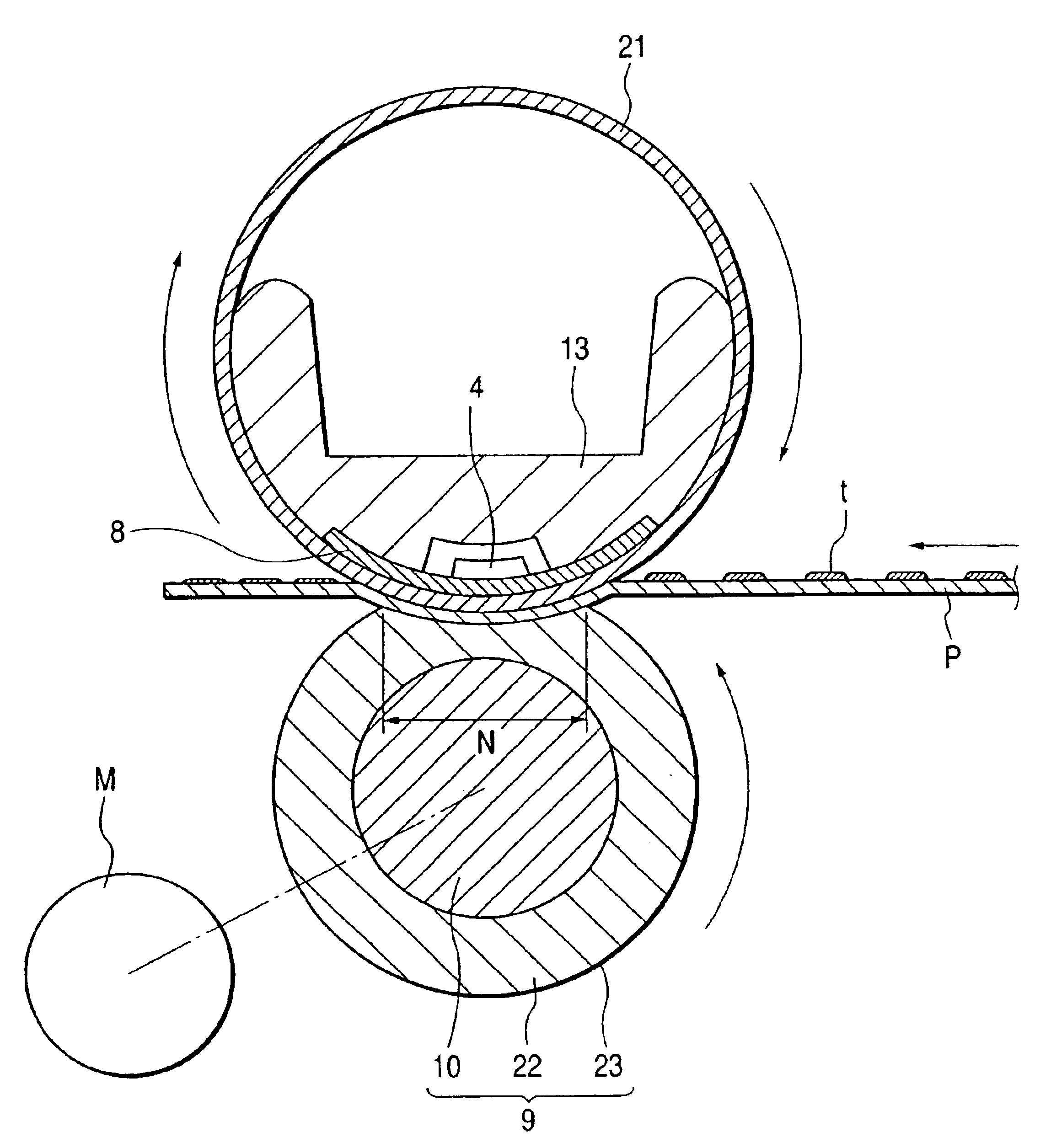
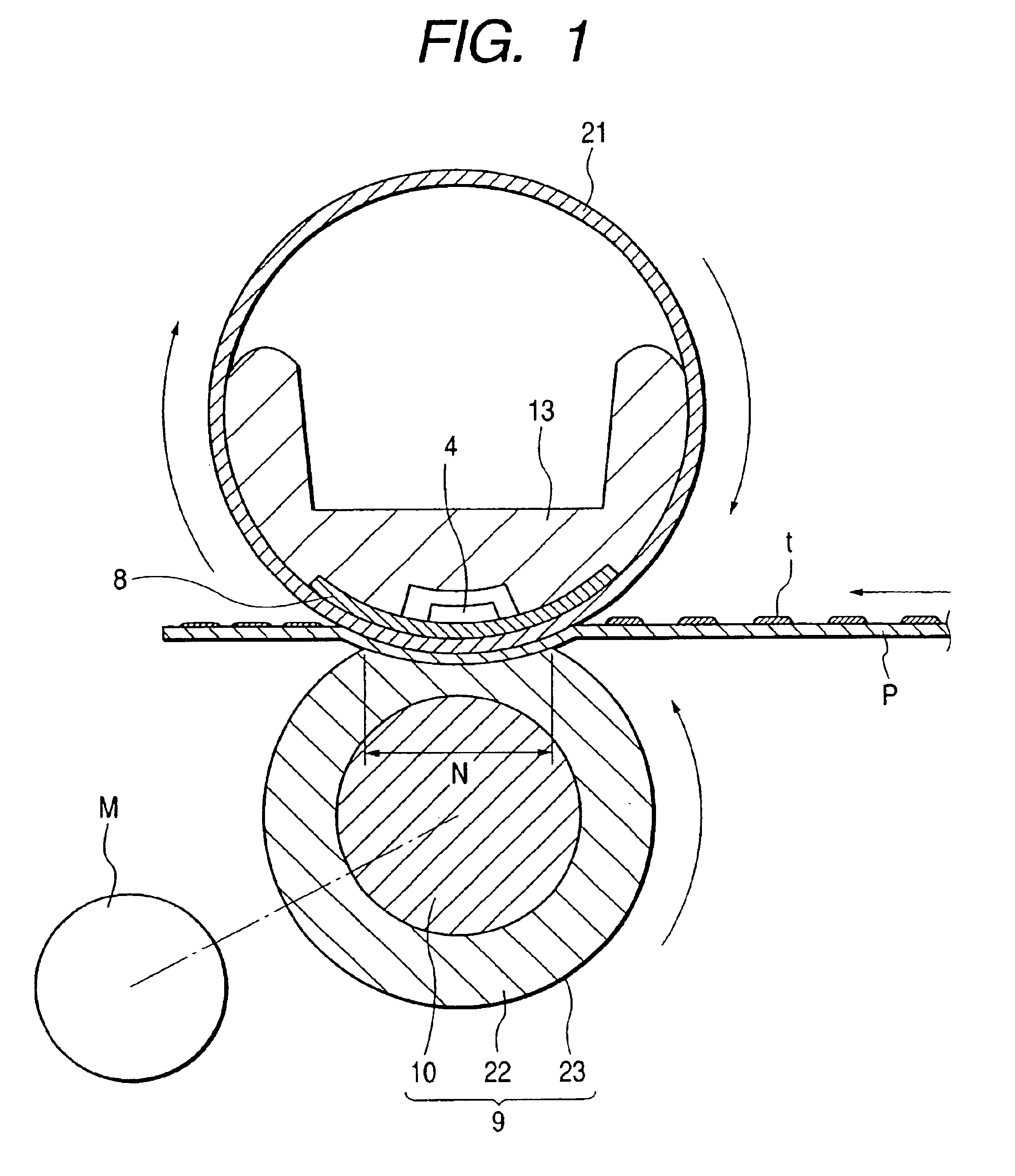
FIG. 1 shows a schematic structural model view (cross-sectional model view) of a heating apparatus in accordance with an embodiment of the present invention.

A heating apparatus according to this embodiment is a pressure roller drive type and film heating type heat-fixing apparatus using a cylindrical (endless type) film basically in the same manner as in the apparatus described in conjunction with FIG. 6. The same reference numerals are used to indicate the like components or members to thereby avoid the duplication of explanation.

The heating apparatus according to this embodiment is characterized in that a curved heater (arch-shaped heater) having a substrate made of metal is used as a heating body 8 and that a film provided with an elastic layer is used as a film 21.

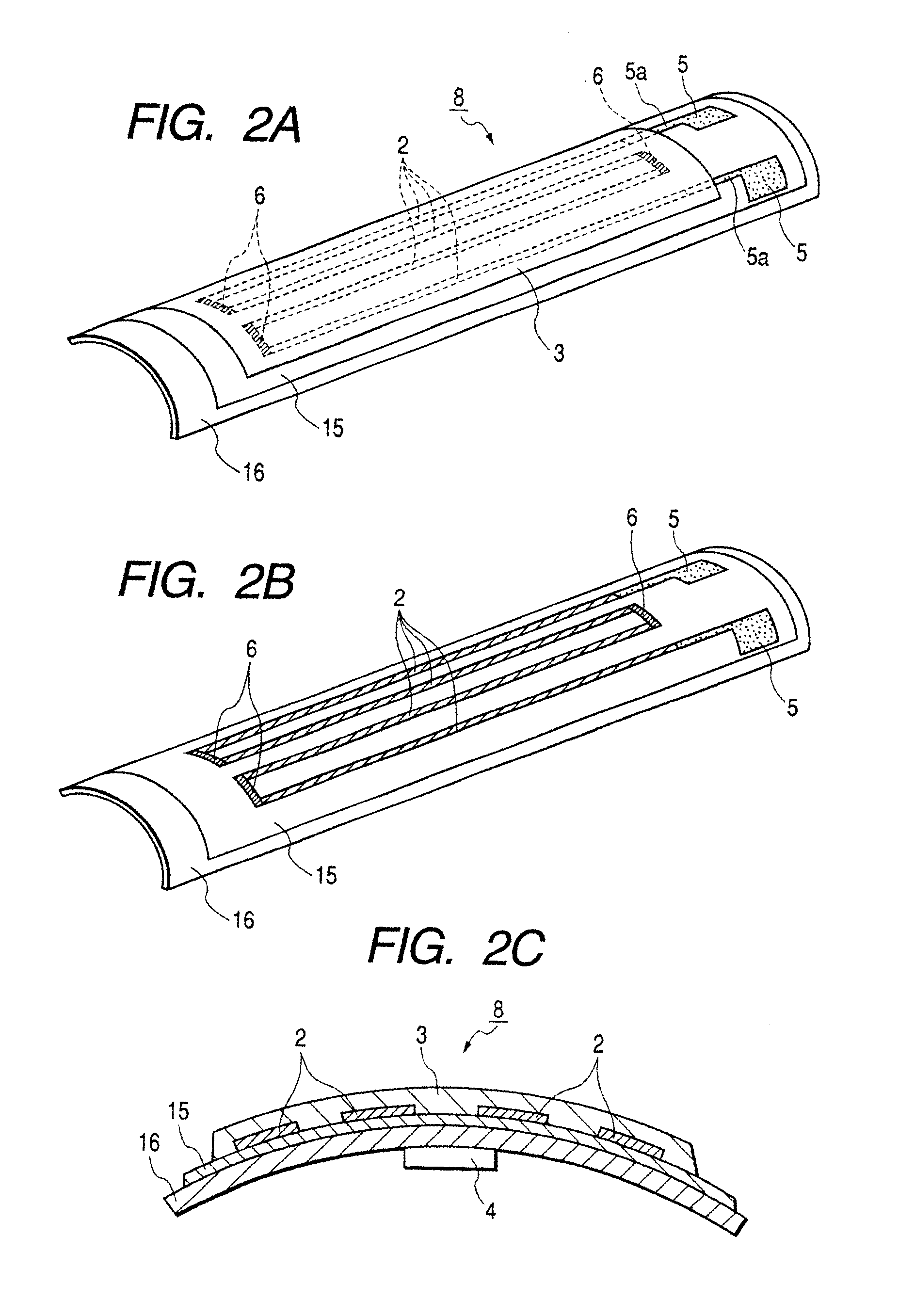
(1) Curved Heater 8

FIGS. 2A to 2C are structural views of the curved heater 8 according to this embodiment. FIG. 2A is a perspective view showing a front surface side of the curved heater 8, FIG. 2B is a perspective vi...

embodiment 2

In the above-described Embodiment 1, the heating body (heater) 8 is formed into a plate-like curved surface. However, a heating body (heater) 8 according to this embodiment takes a cylindrical shape as shown in FIG. 5. Namely, the metallic substrate 16 is formed into a cylindrical shape. Then, the insulating glass layer 15, the resistor pattern 2, the folded electrode 6, the power feeding electrode 5, the conductive pattern 5a that is the extended portion of the power feeding electrode 5 and the surface protective glass layer 3 are printed and backed on the outer surface of this cylindrical metallic substrate 16 in the same manner as in Embodiment 1.

The heater is formed into a cylindrical shape so that the heater per se is used as a support member (stay) for pressurizing to thereby simplify the structure.

Also, since the region in which the area of the resistor pattern 2 may be adjusted as desired is increased, it is possible to cope with the high speed operation.

Conventionally, a su...


PUM


Abstract

An image heating apparatus has a non-rotatable heater with a metallic substrate together with a film that moves in contact with the heater and is accompanied by a backup roller which defines a nip with the heater via the film. The metallic substrate has a cylindrical shape and the heater has a first insulating layer on an outer peripheral surface of the metallic substrate, a heat generating resistor on the first insulating layer and a second insulating layer on the heat generating resistor.

Description

BACKGROUND OF THE INVENTION1. Field of the InventionThe present invention relates to an image heating apparatus and a heater for heating suitably used as a heat-fixing apparatus to be mounted on a copying machine, a printer or the like using a recording technology such as an electrophotographic type or an electrostatic recording type recording technology, and more particularly to an apparatus using a metal substrate as a substrate of a heater.2. Related ArtConventionally, a heat roller type heating device has been extensively used in a device for heat-fixing processing as a permanently fixed image on a recording material surface an unfixed toner image corresponding to target image information formed in a direct manner or an indirect (transfer) manner on a surface of a recording material (an electro-facsimile sheet, an electrostatic recording sheet, a transfer material sheet, a printing sheet or the like) by using toner made of thermally meltable resin or the like by suitable image f...

Claims


Application Information

Patent Timeline
Patent Type & Authority Patents(United States)
IPC IPC(8): G03G15/20H05B3/00H05B3/20H05B3/30
CPCH05B3/0095G03G15/2053
Inventor OTSUKA, YASUMASAKISHINO, KAZUOTAKAHASHI, MASAAKINAKAZONO, YUSUKE
Owner CANON KK
Learn More