Interpolating filter banks in arbitrary dimensions

Inactive Publication Date: 2005-03-08
LUCENT TECH INC
View PDF5 Cites 7 Cited by
  • Summary
  • Abstract
  • Description
  • Claims
  • Application Information

AI Technical Summary

Benefits of technology

The invention provides a general lifting-based technique for building filter banks that works in any dimension, for any type of signal lattice and any number of primal and dual vanishing moments. The invention provides the advantages commonly associated with other lifting-based techniques, such as custom design, in-place computation and integer-to-integer transforms, as well as computation speed, which is particularly important in multid

Problems solved by technology

An important unsolved problem in filter bank design is how to generalize filter banks to process signals in multiple dimensions.
However, these approaches are generally limited to dimensions of two or three, because the algebraic conditions which must be solved to determine filter characteristics become increasingly cumbersome in higher dimensions.
Although systematic approaches based on the McClellan transform and cascade structures also exist, these and the other approaches noted above all fail to provide adequate techniques for designing filter banks in arbitrary dimensions.
Moreover, the above-cited references are primarily directed to techniques for breaking down an existing filter bank into the lifting framework, and thus fail to provide general techniques for designing a filter which has a desired response while also fitting within the lifting framework.

Method used


Image

  • Interpolating filter banks in arbitrary dimensions
  • Interpolating filter banks in arbitrary dimensions
  • Interpolating filter banks in arbitrary dimensions

Examples


Embodiment Construction

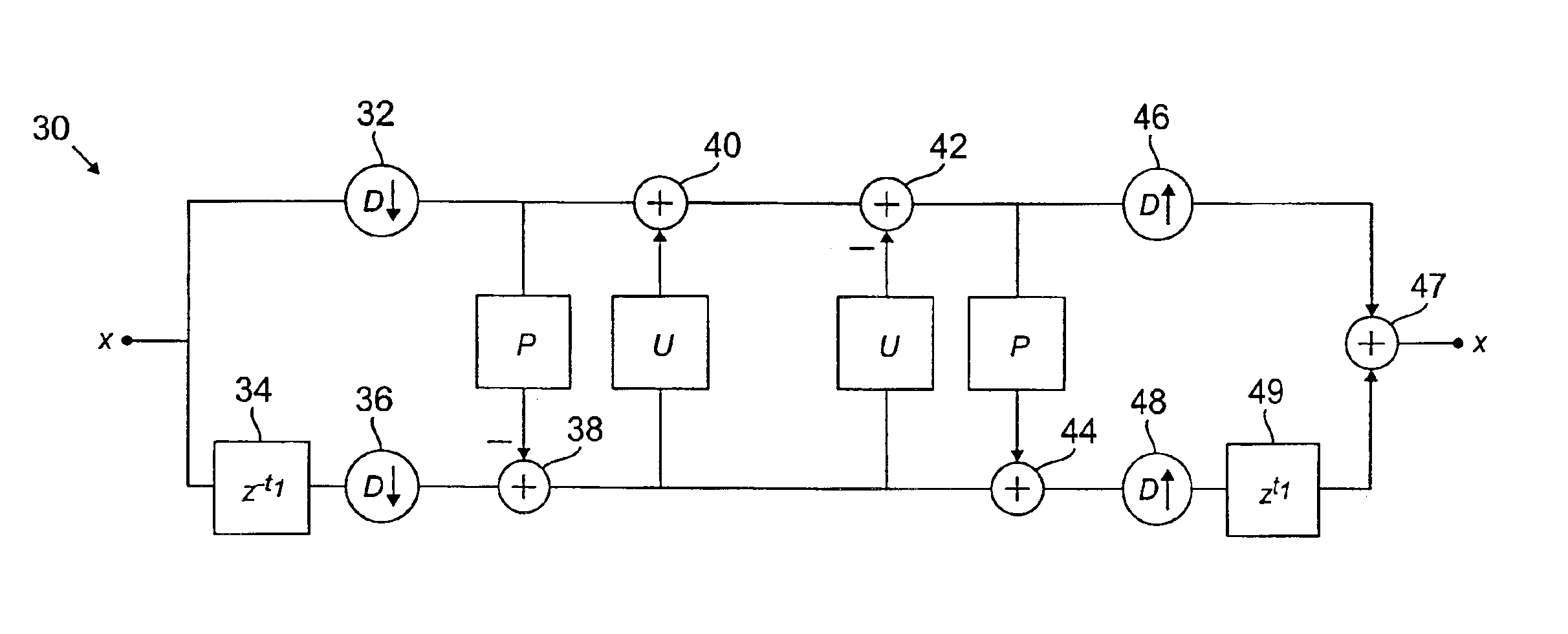
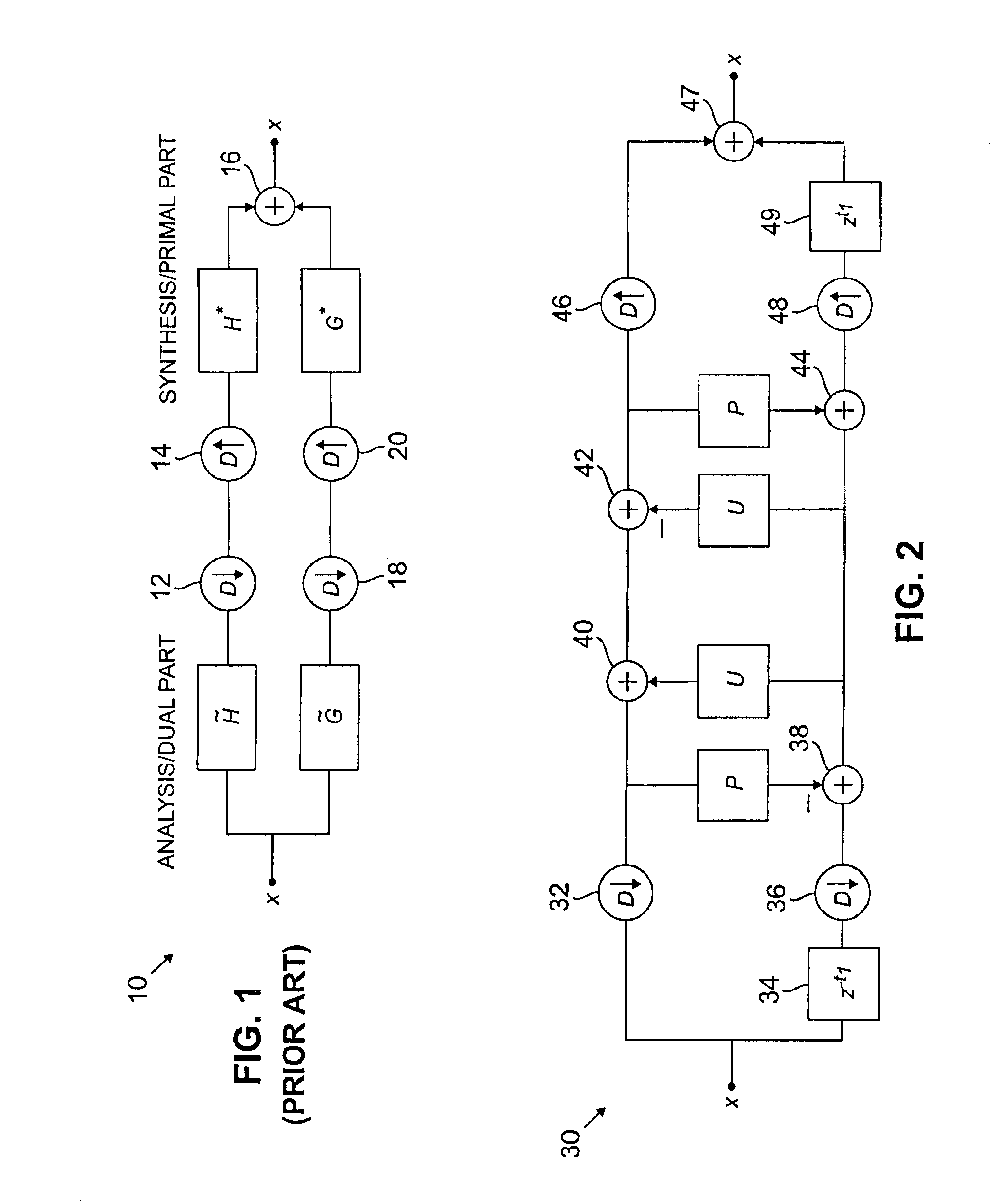
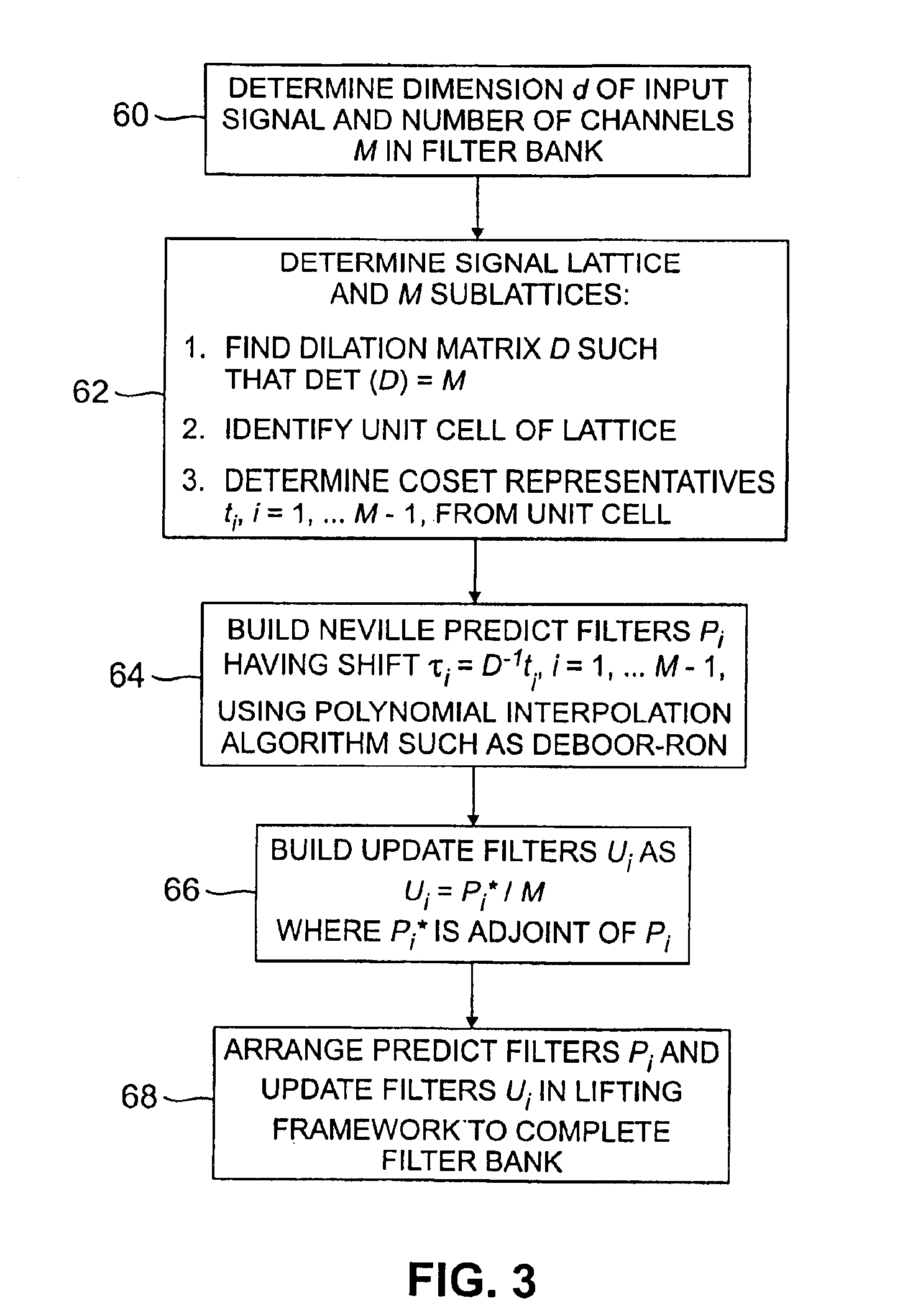
The present invention will be illustrated below in conjunction with exemplary filter banks and signal lattices. It should be understood, however, that the disclosed techniques are suitable for use with a wide variety of other types of signals and in numerous diverse signal processing applications. The term “filter bank” as used herein refers generally to a device for processing a set of samples of a signal. A “lattice” is a representation of signal sample points in one or more dimensions. A “sublattice” is a subset of the sample points of a lattice, and is generally shown in the sampled domain, that is, without other signal sample points which are removed as a result of a downsampling operation. The sublattice typically represents a rotated portion of its corresponding signal lattice. A sublattice is used to identify a particular “neighborhood,” where a neighborhood refers generally to a local subset of sample points in the corresponding sublattice, which is located around a point t...


PUM


Abstract

Interpolating filter banks are constructed for use with signals which may be represented as a lattice of arbitrary dimension d. The filter banks include M channels, where M is greater than or equal to two. A given filter bank is built by first computing a set of shifts τi as D−1 ti, i=1, 2, . . . M−1, where ti is a set of coset representatives taken from a unit cell of the input signal lattice, and D is a dilation matrix having a determinant equal to M. A polynomial interpolation algorithm is then applied to determine weights for a set of M−1 predict filters Pi having the shifts τi. A corresponding set of update filters Ui are then selected as Ui=P*i / M, where P*i is the adjoint of the predict filter Pi. The resulting predict and update filters are arranged in a lifting structure such that each of the predict and update filters are associated with a pair of the M channels of the filter bank. The input signal applied to the filter bank is downsampled in each of the M channels, and then interpolated using the M−1 predict filters and the M−1 update filters. The downsampled and interpolated signal may be reconstructed using complementary interpolation and upsampling operations.

Description

FIELD OF THE INVENTIONThe present invention relates generally to signal processing techniques, and more particularly to interpolating filter banks for use in processing signals which include samples arranged in the form of an arbitrary lattice in any number of dimensions.BACKGROUND OF THE INVENTIONInterpolating filter banks are presently used to process sampled signals in a wide variety of applications, such as video signal processing. A signal put through an interpolating filter bank may be in the form of a multidimensional lattice of sample points. For example, in video applications, an input signal put through the filter bank may be a three-dimensional set of pixels. The interpolating filter bank generally downsamples the input signal, thereby selecting a subset of the signal sample points for further processing. The filter bank includes predict filters for providing an estimate of the sample points which were removed as a result of the downsampling. The output of the predict fil...

Claims


Application Information

Patent Timeline
IPC IPC(8): G06T3/40
CPCG06T3/4084G06T3/4007
Inventor KOVACEVIC, JELENASWELDENS, WIM
Owner LUCENT TECH INC
Why Eureka
Try Eureka