Clarifier cover

a technology for clarifiers and covers, applied in the field of flexible clarifier covers, can solve the problems that the system does not meet all the requirements for a flexible clarifier cover

Inactive Publication Date: 2005-03-15
EVOQUA WATER TECH CANADA LTD
View PDF43 Cites 8 Cited by
  • Summary
  • Abstract
  • Description
  • Claims
  • Application Information

AI Technical Summary

Benefits of technology

In the present invention, however, there is provided a removable clarifier cover which has safety features incorporated therein, w

Problems solved by technology

Although the flexible covers of the prior art deserve undeniable merits, it is believed that these systems do

Method used


Image

  • Clarifier cover
  • Clarifier cover
  • Clarifier cover

Examples


Embodiment Construction

While this invention is susceptible of embodiments in many different forms, there is shown in the drawings and will be described in details herein a specific embodiment, with the understanding that the present disclosure is to be considered as an example of the principles of the invention and is not intended to limit the invention to the embodiment illustrated and described. A number of variant elements are also presented herein to illustrate various manners of construction, installation and operation of the present invention as applied to various clarifier configurations.

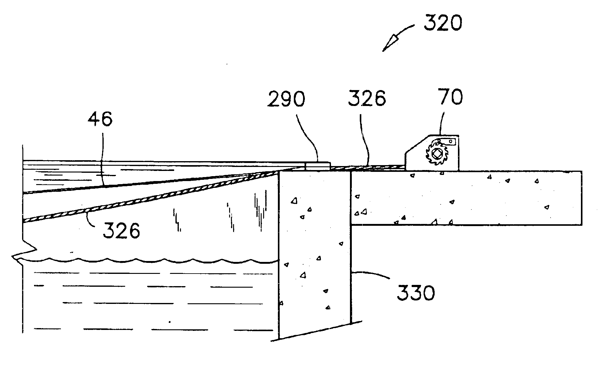
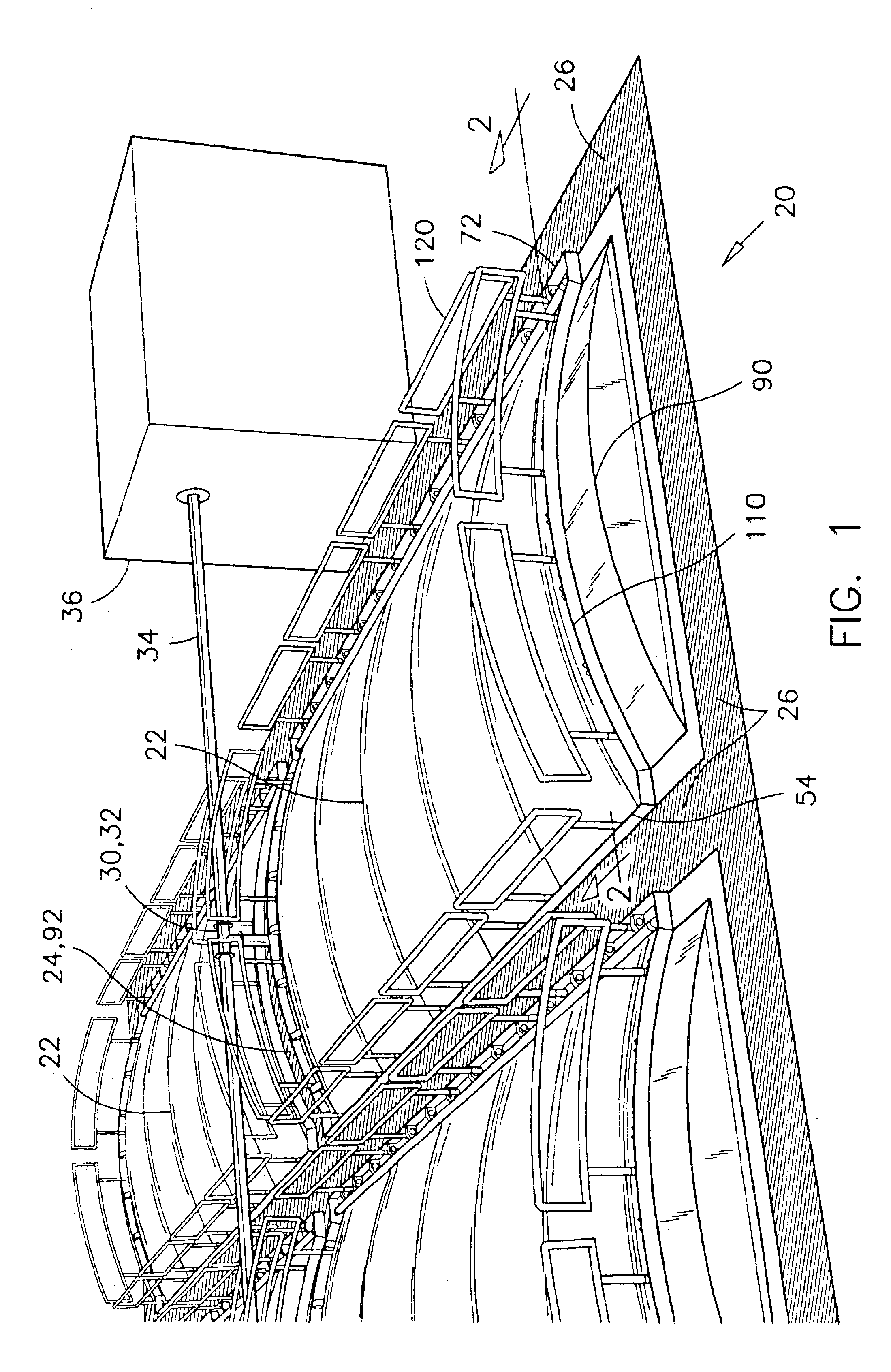
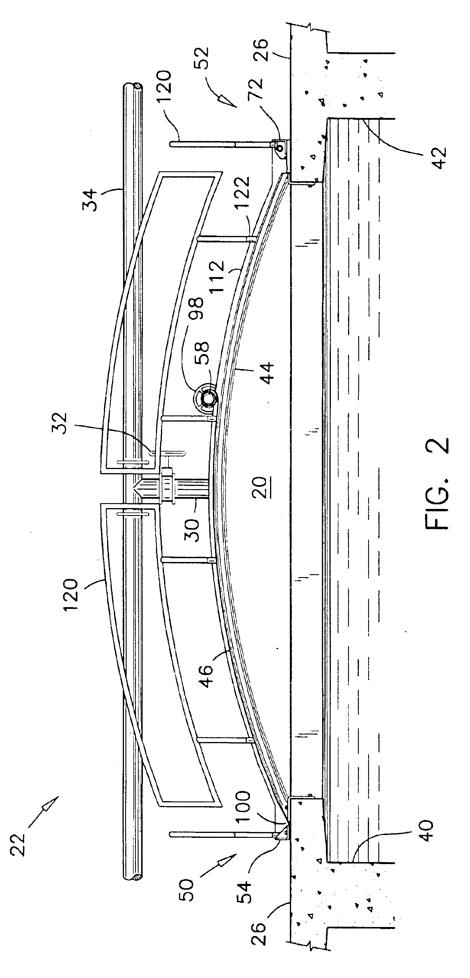
A clarification installation showing juxtaposed reservoirs 20 each being covered by a pair of clarifier covers 22 according to a preferred embodiment of the present invention is illustrated in FIG. 1. In a typical clarification installation, each reservoir or clarifier 20 is divided in two or more sections by one or more intermediate walkways 24. In a preferred installation, each section is covered by a clarifier c...


PUM

PropertyMeasurementUnit
Flexibilityaaaaaaaaaa

Abstract

In the present invention, there is provided a removable cover for retaining off-gases inside a clarifier. The cover comprises trusses extending across the clarifier and a flexible sheet laid across the trusses. Structural angles enclose the clarifier and constitute a kick plate on the walkways around the clarifier for improving the safety of workers. One side of the flexible sheet is permanently affixed to a first wall of the clarifier. A series of pullers are mounted inside the structural angles for pulling and releasably sealing the three other sides of the flexible sheet against the outmost trusses and against a second wall of the clarifier opposite the first wall. Each puller has a cable-deflector bar extending substantially at a same level as a mounting surface of the puller for increasing an angle of downward pull on the flexible sheet. The flexible sheet is rolled-up along the trusses to expose machinery inside the clarifier.

Description

FIELD OF THE INVENTIONThis invention pertains to flexible covers for clarifiers, and more particularly, the present invention pertains to the sealing of a flexible cover over a clarifier for maintaining the content of the clarifier in a sealed environment.BACKGROUND OF THE INVENTIONA typical industrial clarification installation comprises a plurality of reservoirs or holding tanks to be filled with mill effluent. Clarification is normally effected by alternatively agitating and letting the effluent settle, and lifting floating scum from the surface of the effluent or scooping sediments at the bottom of the reservoir. These holding tanks are generally equipped with mechanical equipment that must be accessible for inspection, maintenance or for repair.The clarification process is often accompanied by a fermenting action and a generation of odorous bio-gases, and / or the release of volatile organic carbons. For environmental reasons, these gases must be collected and treated. Therefore,...

Claims


Application Information

Patent Timeline
IPC IPC(8): B01D21/00B01D17/02E04H4/10E04H4/00
CPCB01D17/0208E04H4/108B01D21/0003
Inventor MACLEAN, BRIANHOWE, BRENT M.
Owner EVOQUA WATER TECH CANADA LTD
Why Eureka
Try Eureka