Sponge mop assembly

a technology of sponge mop and assembly, which is applied in the field of sponge mop, can solve the problems of user easily getting exhausted or even hurting his/her wais

Inactive Publication Date: 2005-03-15
CHENG CHIN TING
View PDF8 Cites 13 Cited by
  • Summary
  • Abstract
  • Description
  • Claims
  • Application Information

AI Technical Summary

Benefits of technology

Accordingly, the objective of the present invention is attained by a sponge mop assembly comprising a handle, a head, a pull rod assembly, and a brushing member. The head includes a mount clamping a sponge and mounted to a bottom end of the handle, two front coupling arms extending bilaterally downward from a front side of the mount such that a space is defined between the mount and the front coupling arms, and two rear coupling arms extending bilaterally downward from a rear side of the mount. Two parallel front squeezing members are mounted side by side between the two front coupling arms and two parallel rear squeezing members are mounted side by side between the two rear coupling arms. The pull rod assembly is mounted on the handle and connected with the sponge for moving the sponge to be squeezed by the squeezing members so as to remove water from the sponge. The brushing member is mounted on a front side of the mount and is located in the space. Therefore, the sponge mop assembly of the present invention is provided with both functions of mopping and brushing the floor as well as being user-friendly.

Problems solved by technology

However, such kind of sponge mop can be used only for mopping the floor instead of any extra functions.
Meanwhile, the user may easily get exhausted or even hurt his / her waist.

Method used


Image

  • Sponge mop assembly
  • Sponge mop assembly
  • Sponge mop assembly

Examples


Embodiment Construction

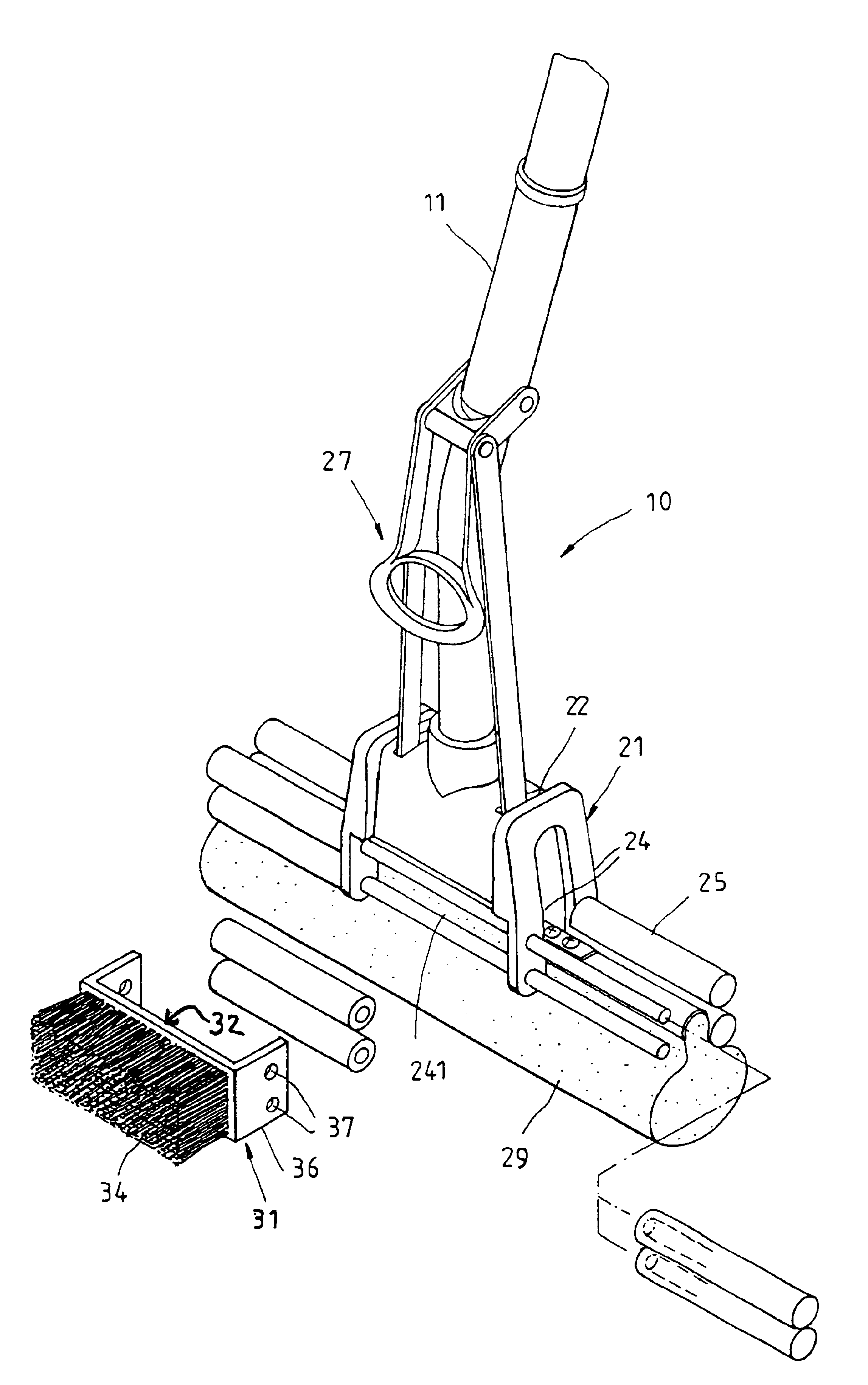
Referring to FIGS. 4-5, a sponge mop assembly 10 of a preferred embodiment of the present invention is composed of a handle 11, a head 21, a pull rod assembly 27, and a scrubbing or brushing member 31.

The handle 11 has a predetermined length for operation.

The head 21 includes a mount 22 clamping a sponge 29 and mounted to a bottom end of the handle 11, two front coupling arms 24 bilaterally extending downward from a front side of the mount 22, and two rear coupling arms bilaterally extending from a rear side of the mount 22, such that a space 241 is defined between the front side of the mount 22 and the two front coupling arms 24. Two parallel front squeezing members 25 are mounted side by side between the two front coupling arms 24 and two parallel rear squeezing members 25 are mounted side by side between the two rear coupling arms. The pull rod assembly 27 is pivotally mounted on the handle 11 and is connected with the sponge 29 such that the sponge 29 is actuated by the pull rod...


PUM


Abstract

A sponge mop assembly includes a handle and a head mounted on a bottom end of the handle. The head has a mount clamping a sponge, two front and two rear coupling arms bilaterally extending downward from front and rear sides of the mount such that a space is defined between the mount and the front coupling arms, and two parallel front and two parallel rear squeezing members mounted side by side between the two front and rear coupling arms. A pull rod assembly is mounted on the handle and connected with the sponge for moving the sponge to be squeezed by the squeezing members so as to remove water from the sponge. A brushing member is mounted on a front side of the mount and located in the space. Therefore, the sponge mop assembly is provided with both functions of mopping and brushing the floor as well as being user-friendly.

Description

FIELD OF THE INVENTIONThe present invention relates generally to a sponge mop, and more particularly to a sponge mop assembly provided with a function of brushing the floor.BACKGROUND OF THE INVENTIONAs shown in FIG. 1, a conventional sponge mop 70 includes a handle 71, a head 72 fastened to a bottom end of the handle 71, and a pull rod assembly pivotally 76 mounted to the handle. The head 72 is composed of a mount 73 clamping a sponge 74, which is bilaterally clamped by two shaft rods 75 and is actuated to move inward between the shaft rods 75 by the pull rod assembly 76 so as to squeeze out water contained in the sponge 74. However, such kind of sponge mop can be used only for mopping the floor instead of any extra functions.Another conventional mop 80 as shown in FIG. 2 includes the handle 81 curved at a bottom section of the mop 80. The mount 82 of the mop 80 has a front side panel 83 provided with threaded holes 84 therethrough. A brushing member 86 has a mounting panel 87, whi...

Claims


Application Information

Patent Timeline
Patent Type & Authority Patents(United States)
IPC IPC(8): A47L13/10A47L13/12A47L13/144
CPCA47L13/144A47L13/12
Inventor CHEN, HWA-TIEN
Owner CHENG CHIN TING
Why Eureka
Try Eureka