Fuel cell module with a water reservoir including a water storing portion expanding from a cell unit to an anode side

a fuel cell module and water reservoir technology, applied in the direction of fuel cells, fuel cell details, solid electrolyte fuel cells, etc., can solve the problems of reducing output, conventional fuel cells requiring extra space in the entirety, and reducing output, so as to achieve stable output of the fuel cell module

Inactive Publication Date: 2014-08-05
JX NIPPON OIL & ENERGY CORP
View PDF9 Cites 1 Cited by
  • Summary
  • Abstract
  • Description
  • Claims
  • Application Information

AI Technical Summary

Benefits of technology

[0011]According to this embodiment, the water produced at the cathode can be collected in the water reservoir provided in a region other than the cathode, so that the water can be removed from the surface of the cathode. This makes it hard for the cathode to be covered by the water it has produced, and there is thus little impediment to the supply of the oxidant, such as air, to the cathode. As a result, the fuel cell module can achieve a stable output over a long period of time.
[0020]Fuel used for the anode may be a liquid fuel which at least contains methanol, and the cell unit may be provided with a restraining membrane, on an anode-side surface of the electrolyte membrane other than that of the anode, which restrains methanol from permeating therethrough. This may prevent the so-called methanol crossover in which methanol travels from the anode side including the water reservoir directly to the cathode side even when the fuel is a liquid fuel containing methanol.

Problems solved by technology

That is, when water produced at the cathode (air electrode) is excessive, the water covering the cathode may interfere with an adequate supply of the oxidant, such as air, to the cathode, thus leading to an output decline.
However, such conventional fuel cells require extra space in the entirety of a fuel cell because it is necessary to have a water retention or water storage unit in the lateral or external part thereof.
Furthermore, the conventional water-conducting member, which is provided in such a manner as to cover the whole cathode, can cause a drop in output by obstructing the diffusion of air to the cathode electrode.

Method used


Image

  • Fuel cell module with a water reservoir including a water storing portion expanding from a cell unit to an anode side
  • Fuel cell module with a water reservoir including a water storing portion expanding from a cell unit to an anode side
  • Fuel cell module with a water reservoir including a water storing portion expanding from a cell unit to an anode side

Examples


first embodiment

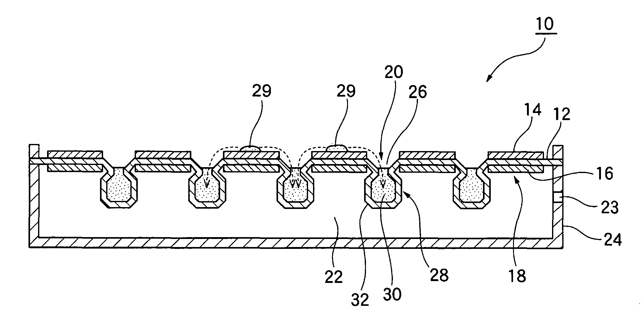
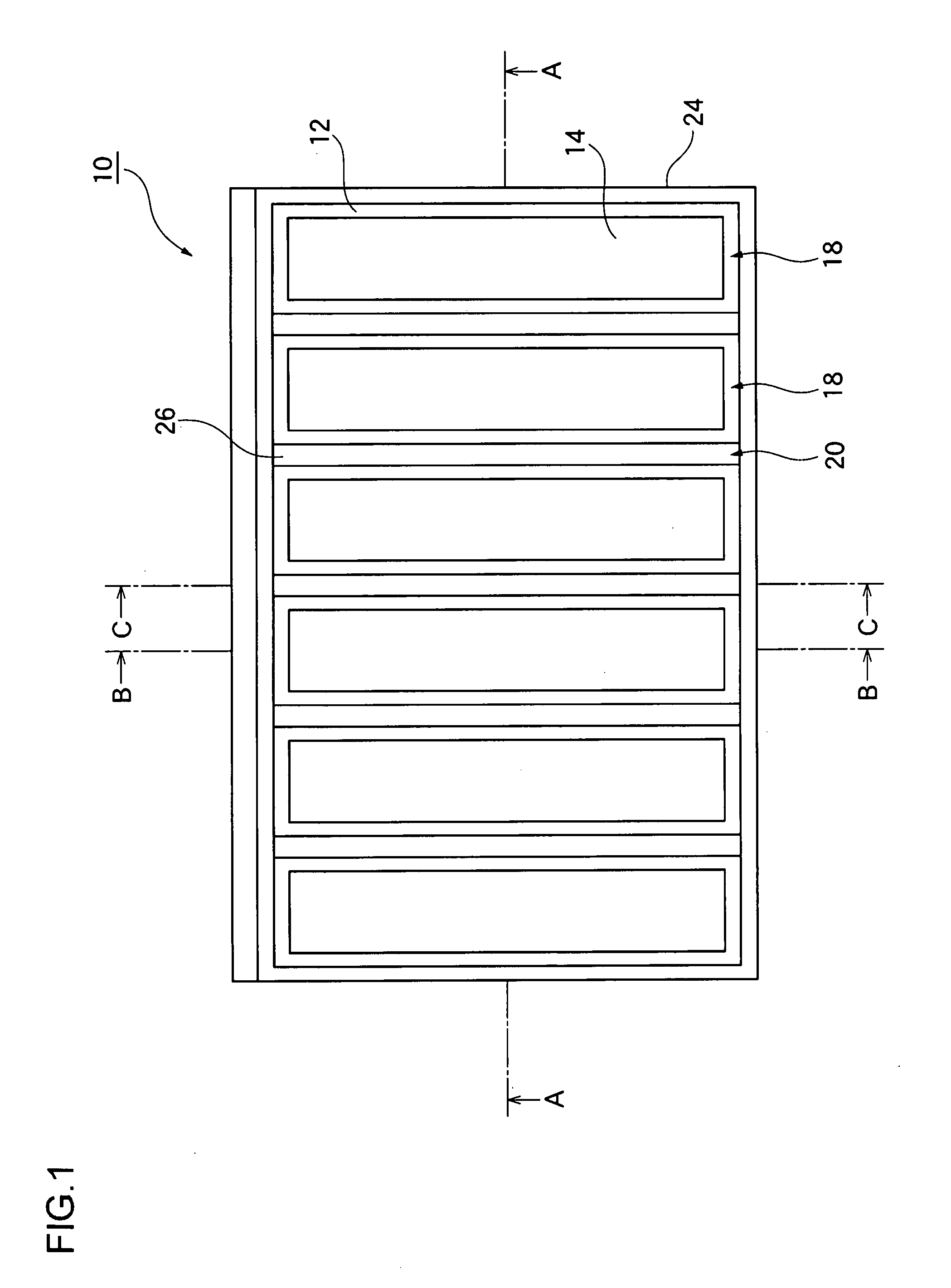
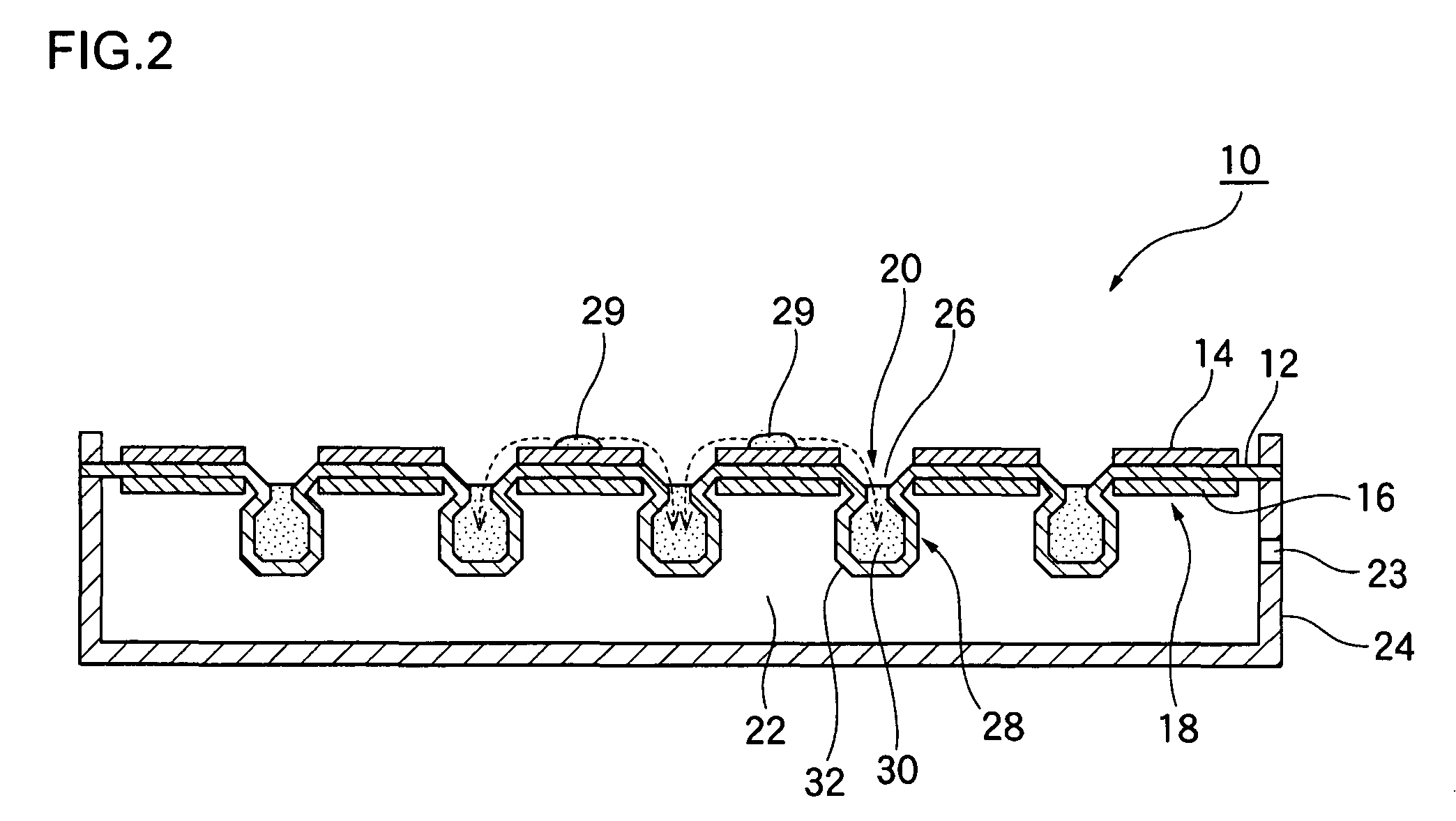
[0037]FIG. 1 is a top view schematically illustrating a structure of a fuel cell module according to a first embodiment of the present invention. FIG. 2 is a cross-sectional view taken along the line A-A of the fuel cell module of FIG. 1.

[0038]As illustrated in FIG. 1 and FIG. 2, a fuel cell module 10 according to the first embodiment includes a plurality of cell units 18, each of which comprises a solid polymer electrolyte membrane 12, a cathode 14 disposed on one face of the electrolyte membrane 12, and an anode 16 disposed on the other face thereof, water reservoirs 20 for collecting water 29 produced at the cathodes 14, and a fuel chamber 22 disposed on the anode side for storing a fuel to be supplied to the anodes 16. Note that the cathodes 14 and the anodes 16 are each comprised of a catalyst layer, a gas diffusion layer, and a current collector (all not shown) which are integrally structured together.

[0039]The fuel chamber 22 is formed by the electrolyte membrane 12 of cell u...

second embodiment

[0055]A fuel cell module according to a second embodiment of the present invention differs from the fuel cell module 10 of the first embodiment in that the opening of a water reservoir is formed in the cathode of a cell unit. FIG. 10 is a top view schematically illustrating a structure of a fuel cell module according to the second embodiment. FIG. 11 is a cross-sectional view taken along the line A′-A′ of the fuel cell module of FIG. 10.

[0056]As illustrated in FIG. 10 and FIG. 11, a fuel cell module 50 according to this second embodiment includes a plurality of cell units 58, each of which comprises a solid polymer electrolyte membrane 52, a cathode 54 disposed on one face of the electrolyte membrane 52 and an anode 56 disposed on the other face thereof, water reservoirs 60 for collecting water 69 produced at the cathodes 54, and a fuel chamber 62 disposed on the anode side for storing a fuel to be supplied to the anodes 56. Note that the cathodes 54 and the anodes 56 are each compr...

third embodiment

[0060]When power generation by a fuel cell module lasts a long time, there may be cases where water is produced at the cathodes in excess of the water retention capacity of the water-absorbing member thereof. To solve this problem, a fuel cell module 110 according to a third embodiment of the present invention is so configured that at least one part of the water-absorbing member is detachable from the water reservoir.

[0061]FIG. 7 is an exploded perspective view of a fuel cell module according to the third embodiment. The fuel cell module 110 includes a plurality of cell units 118, each of which comprises a solid polymer electrolyte membrane 112, a cathode 114 disposed on one face of the electrolyte membrane 112, and an anode (not shown) disposed on the other face thereof, water reservoirs 120 for collecting water produced at the cathodes 114, and a fuel chamber 122 disposed on an anode side for storing a fuel to be supplied to the anodes.

[0062]The water reservoir 120 includes an ope...


PUM

PropertyMeasurementUnit
temperaturesaaaaaaaaaa
areaaaaaaaaaaa
cell voltageaaaaaaaaaa

Abstract

A fuel cell module includes a cell unit including an electrolyte membrane, a cathode disposed on one face of the electrolyte membrane, and an anode disposed on the other face of the electrolyte membrane, and a water reservoir which stores water produced at the cathode. The water reservoir includes an opening formed in a region other than the cathode of the cell unit, and a projection projecting from the opening to an anode side. The water covering a cathode surface of a fuel cell is reduced.

Description

CROSS-REFERENCE TO RELATED APPLICATIONS[0001]This application is based upon and claims the benefit of priority from the prior Japanese Patent Application No. 2007-084890, filed on Mar. 28, 2007, the entire contents of which are incorporated herein by reference.BACKGROUND OF THE INVENTION[0002]1. Field of the Invention[0003]The present invention relates to a fuel cell module.[0004]2. Description of the Related Art[0005]Recently much attention has been focused on fuel cells that feature not only high energy conversion efficiency but also no hazardous substance produced by the electricity-generating reaction. Known as one of such fuel cells is the polymer electrolyte fuel cell (PEFC) which operates at temperatures below 100° C. As known types of the polymer electrolyte fuel cell (PEFC), there are, for instance, one using hydrogen as the fuel and another, called direct methanol fuel cell (DMFC), in which methanol water solution as the fuel is not reformed but is directly supplied to the...

Claims


Application Information

Patent Timeline
Patent Type & Authority Patents(United States)
IPC IPC(8): H01M8/02H01M8/04H01M8/10
CPCH01M8/04156H01M8/04171H01M2008/1095Y02E60/50Y02E60/523
Inventor TANIGUCHI, SHUNSUKEISONO, TAKAHIRO
Owner JX NIPPON OIL & ENERGY CORP
Why Eureka
Try Eureka