
Torque testing device

Inactive Publication Date: 2005-03-15
EDUARD WILLE GMBH & CO KG
View PDF21 Cites 10 Cited by
  • Summary
  • Abstract
  • Description
  • Claims
  • Application Information

AI Technical Summary

Benefits of technology

It is another object of the invention to design a testing device of the type mentioned in the beginning such that interferences are avoided.
It is still another object of the invention to design a testing device of the type mentioned in the beginning such that the risk of operating errors is minimized.
Thus, the invention provides a plurality of measuring heads, which either may have different measuring ranges or may be adapted to different tools to be tested. Each of these measuring heads has its own signal processing means. The signal processing means are calibrated in the same way, such that the torque measuring data of different measuring heads can be compared with each other. A certain torque T acting on one measuring head provides the same torque data at the measuring head signal output of this measuring head as the torque T would provide at the measuring head signal output of another measuring head. 1 Nm (Newton meter) at one measuring head would provide also 1 Nm at the other measuring head. When calibrating a measuring head, the individual signal processing means can also be adjusted to take individual non-linearities of the torque sensors into account. The measuring heads can then simply be connected in parallel with the display or evaluation means. If a torque is exerted on any one of the measuring heads, this torque will automatically be displayed or evaluated with the correct calibration. The use of individual signal processing means in each measuring head represents an additional expenditure. This expenditure is, however, largely compensated for by saving expensive measures for shielding or suppression of interferences and by saving selector switch means. The invention offers the advantage of simplified handling and reduction of the risk of operational errors.

Problems solved by technology

The transmitting of the analog signal to the display or evaluation means involves the risk of the signal being falsified by interferences.
Connecting or switching measuring heads to the display or evaluation means is complex and may result in operating errors.

Method used


Image

  • Torque testing device
  • Torque testing device
  • Torque testing device

Examples


Embodiment Construction

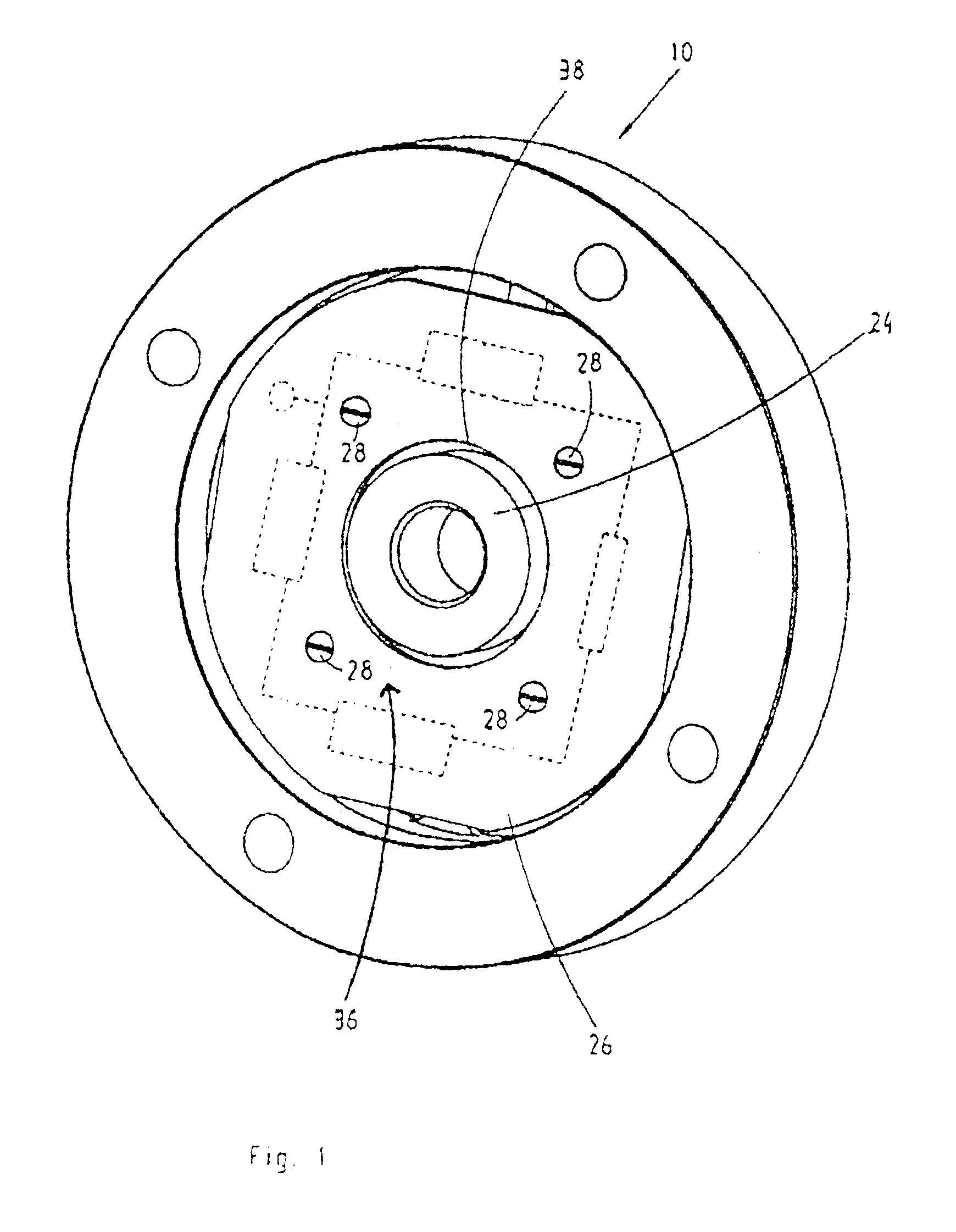
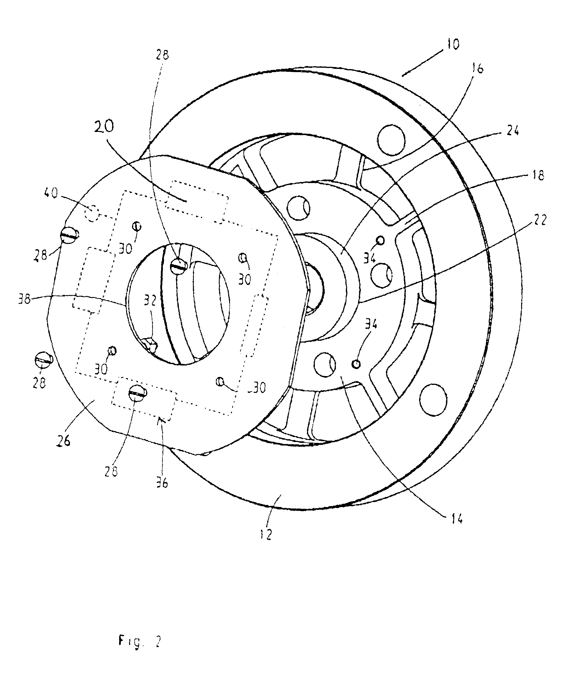
Referring to FIGS. 1 and 2, numeral 10 generally designates a torque sensor. As can be seen best from FIG. 2, the torque sensor 10 comprises an outer annular body 12 and an inner annular body 14. Outer and inner annular bodies 12 and 14, respectively, are interconnected by radial webs 16 and 18. The webs 16 have relatively large width in circumferential direction but have relatively small axial dimensions. The axial dimensions of the webs 16 are substantially smaller than the axial thickness of the outer annular body 12. The webs 18 are narrow in circumferential direction but extend, in axial direction, through nearly the whole thickness of the outer annular body. Wide and narrow webs 16 and 18, respectively, alternate. The webs 16 and 18 are arranged in regular arrangement with an annular offset of 45° between each pair of neighboring webs 16 and 18, whereby a cross of four wide webs 16 is formed, which are angularly spaced by 90°. The wide webs 18 carry strain gages 20, which are ...


PUM


Abstract

The invention relates to a testing device for measuring torques with a sensor for generating electrical signals in response to exerted torques, and signal processing means, to which the electrical signals are applied and which provide measuring values of the exerted torque. The invention provides a plurality of measuring heads, which either may have different measuring ranges or may be adapted to different tools to be tested. Each of these measuring heads has its own signal processing means. The signal processing means are calibrated in the same way, such that the torque measuring data of different measuring heads can be compared with each other. When calibrating a measuring head, the individual signal processing means can also be adjusted to take individual non-linearities of the torque sensors into account. The measuring heads can then simply be connected in parallel with the display or evaluation means. If a torque is exerted on anyone of the measuring heads, this torque will automatically be displayed or evaluated with the correct calibration.

Description

The invention relates to a testing device for measuring torques comprising sensor means for generating electrical signals in response to exerted torques, and signal processing means, to which the electrical signals are applied and which provide measuring values of the exerted torque.BACKGROUND OF THE INVENTIONSuch measuring heads are, for example, to be used to calibrate torque wrenches. The sensor means, conventionally, have strain gages. These strain gages are cemented to parts which are deformed by the torque to be measured. Such strain gages provide weak, analog signals. Usually, these analog signals are not exactly proportional to the torque exerted on the torque sensor. Therefore, signal processing is necessary to obtain a signal which exactly represents the torque. This signal is displayed by display means or is otherwise supplied to evaluation means, for example, for determining the variation in time or the statistical distribution of the torques.Each torque sensor has a lim...

Claims


Application Information

Patent Timeline
IPC IPC(8): G01L3/02G01L3/14
CPCG01L3/1457
Inventor HERBOLD, SIEGFRIED
Owner EDUARD WILLE GMBH & CO KG
Features
  • Generate Ideas
  • Intellectual Property
  • Life Sciences
  • Materials
  • Tech Scout
  • Unparalleled Data Quality
  • Higher Quality Content
  • 60% Fewer Hallucinations
Learn More