
Electrical connector assembly

a technology of electrical connectors and connector parts, applied in the direction of incorrect coupling prevention, coupling device connection, electrical apparatus, etc., can solve the problem of low tolerance for position errors during mating, large errors, and insufficient precision of the guide mechanism providing this level of rough guid

Inactive Publication Date: 2005-03-15
FUJITSU LTD +1
View PDF12 Cites 42 Cited by
  • Summary
  • Abstract
  • Description
  • Claims
  • Application Information

AI Technical Summary

Benefits of technology

These types of electrical connector assemblies in which male contact sections consisting of substrates (chicklets) are connected with female terminals of the mating connector have a low tolerances for position errors during mating. Thus, the first connector and second connector must be aligned fairly precisely before mating. Then, final positioning is performed accurately with the help of the guide mechanism attached to the electrical connector assembly.

Problems solved by technology

These types of electrical connector assemblies in which male contact sections consisting of substrates (chicklets) are connected with female terminals of the mating connector have a low tolerances for position errors during mating.
On the other hand, the technique disclosed in JP 3058235 provides a fairly rough guide and permits fairly large errors in the positioning of the two connectors in the initial stage of mating.
However, a guide mechanism which provides this level of rough guide does not have sufficient precision when used in a connector having substrates (chicklets) forming male contacts.

Method used


Image

  • Electrical connector assembly
  • Electrical connector assembly
  • Electrical connector assembly

Examples


Embodiment Construction

Embodiments of the present invention will be described below with reference to the drawings.

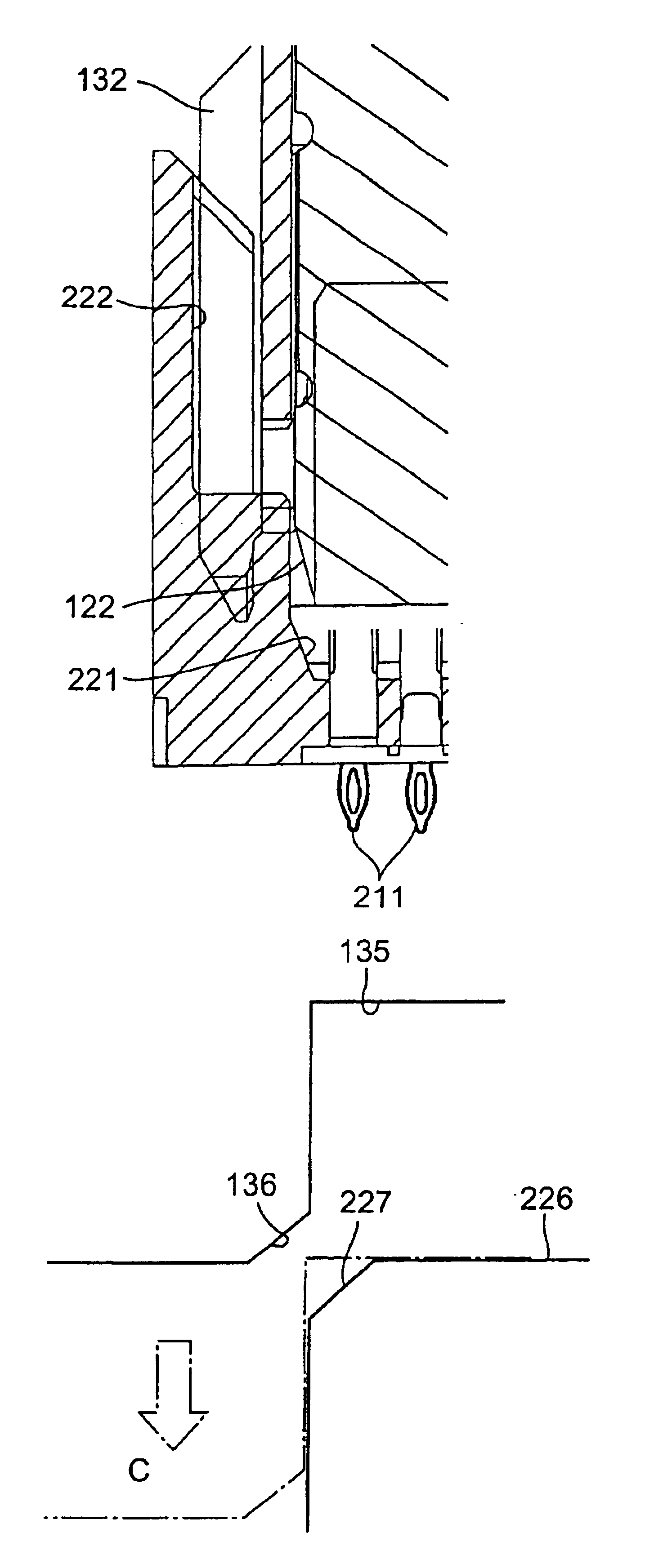
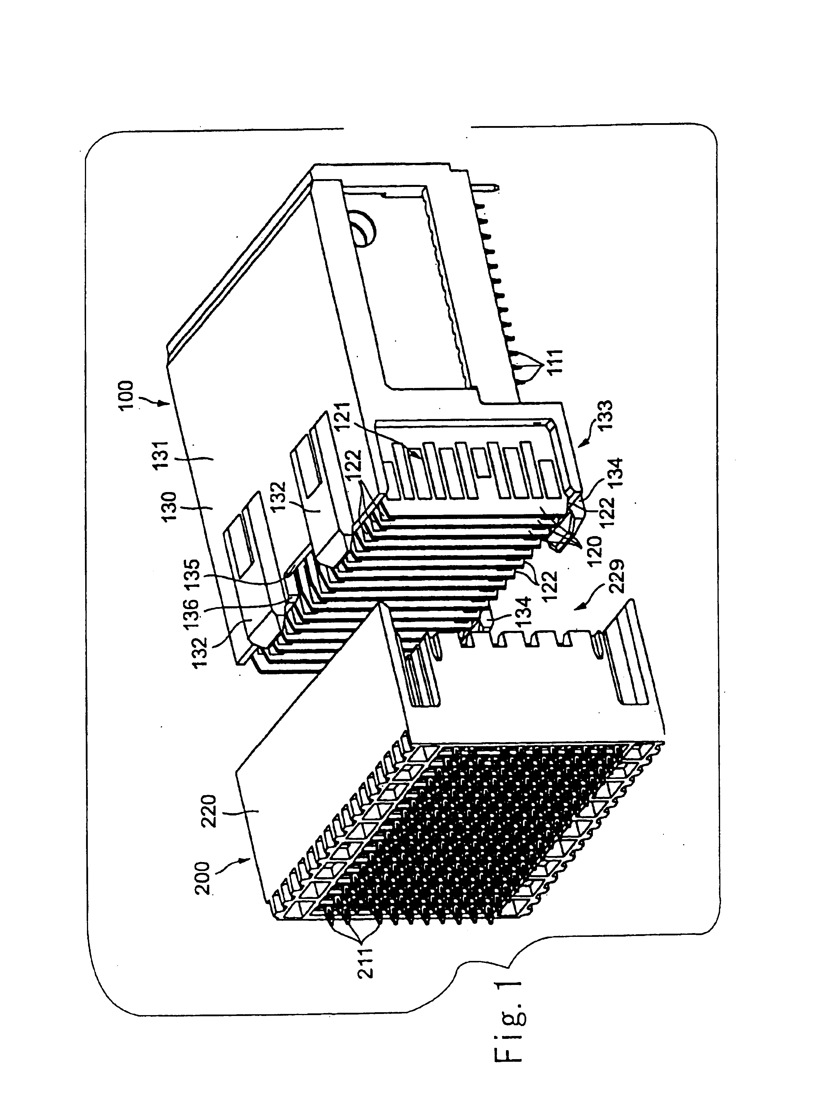
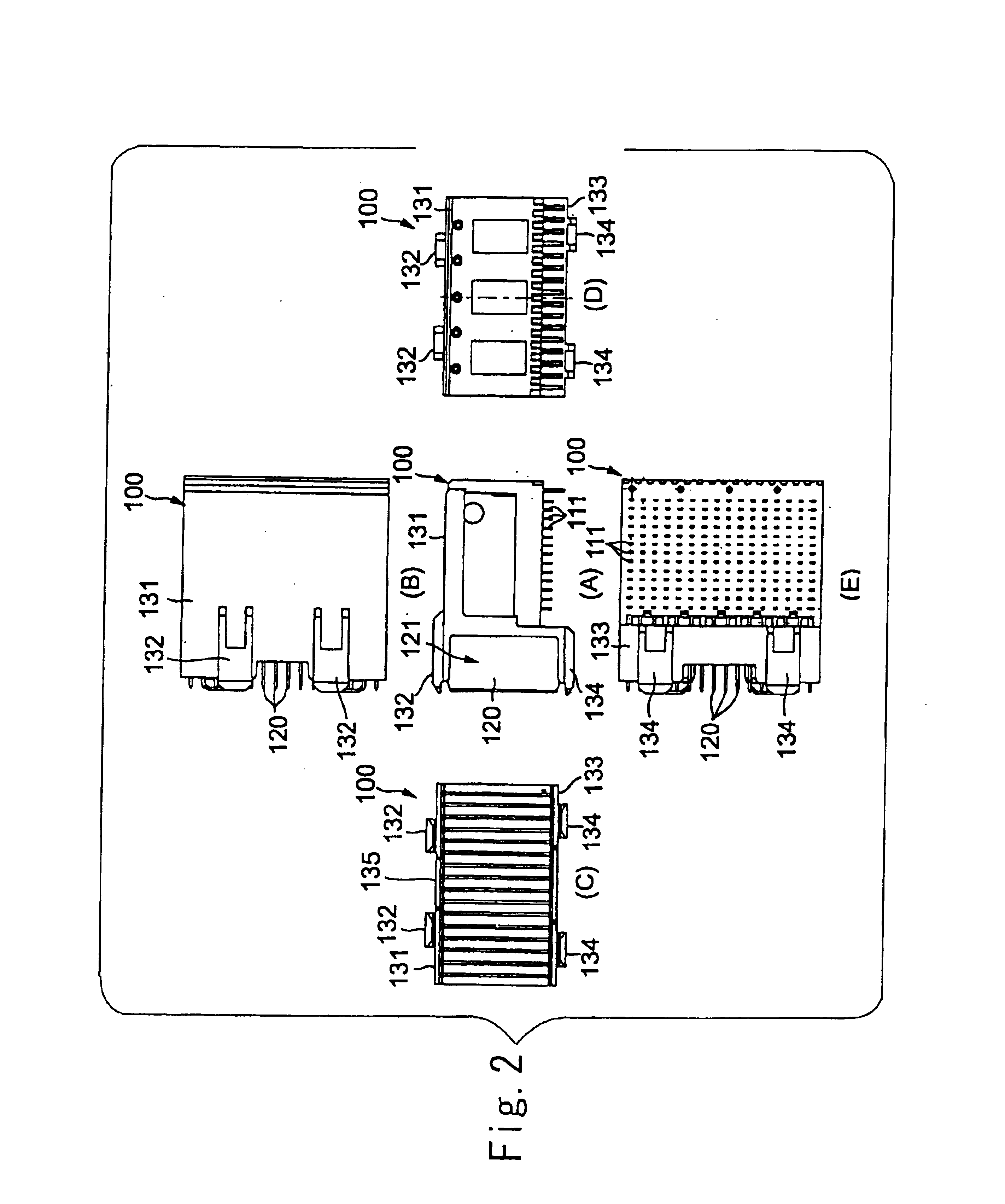
Referring to FIGS. 1 and 9, the first connector 100 includes terminals 110 equipped with compliant pins 111 which are received in through-holes of a daughter board (not shown), multiple substrates (chicklets) 120 arranged in an array, and a housing 130 which secures the multiple substrates 120 in an array.

The second connector 200 as shown in FIGS. 1, 3 and 11 is provided with compliant pins 211 received in through-holes of a motherboard to be connected with the daughter board via the first and second connectors 100 and 200. It includes, multiple female terminals 210 which engage contact sections 121 (see FIG. 7) provided on the substrates 120 of the first connector 100 and a housing 220 which secures the multiple female terminals 210 and has a mating surface 229 (see FIG. 3) to accept the first connector 100.

The terminals 110 of the first connector 100 are arranged in a two-dimensional array ...


PUM


Abstract

The present invention relates to an electrical connector assembly capable of achieving a high-precision fit starting with fairly rough positioning, the assembly consisting of a first connector which is equipped with multiple substrates secured in an array and a second connector which is equipped with female terminals and mates with the first connector. The electrical connector has a rough guide mechanism (first guides and second guides as well as first complementary guides and second complementary guides) which guides a mating between the first connector and the second connector relatively roughly at an initial stage of mating, and a precision guide mechanism (chamfers on substrates and corresponding tapers on a housing of the second connector) which guides the mating between the first connector and the second connector relatively precisely at an advanced stage of mating.

Description

FIELD OF THE INVENTIONThe present invention relates to an electrical connector assembly having a first connector equipped with multiple substrates secured in an array and a second connector equipped with female terminals for mating with the first connector.BACKGROUND OF THE INVENTIONElectrical connector assemblies which consist of a first connector having multiple substrates known as chicklets secured in an array and a second connector equipped with female terminals have been used for electrically connecting multiple circuit boards. For example, a circuit board called a mother board and a circuit board known as a daughter board may be electrically connected to each other in this manner. U.S. Pat. No. 6,384,341, hereinafter '341, discloses an electrical connector assembly which consists of a first connector having multiple terminals, multiple substrates equipped with lands connected to the terminals and contact sections to be connected to a mating connector. A first housing supports ...

Claims


Application Information

Patent Timeline
IPC IPC(8): H01R13/629H01R13/64H01R13/631
CPCH01R12/7005H01R13/629H01R13/631
Inventor KIMURA, TAKESHIORUI, KAZUYASHIMIZU, KUNIHIKOOTAGURO, HIROYUKITAKADA, RIE
Owner FUJITSU LTD
Learn More