Temporary protective cover for an electrical box

Inactive Publication Date: 2005-03-15
COMPAGNONE JR CARLO
View PDF14 Cites 47 Cited by
  • Summary
  • Abstract
  • Description
  • Claims
  • Application Information

AI Technical Summary

Benefits of technology

It is another object of the present invention to provide a cover as described above which can removably mounted onto an electrical box which, in turn, can be used as a mounting structure for installing an electrical device, such as an outlet, switch or fixture, into a covering, such as a wall or ceiling panel.
It is yet another object of the present invention to provide a cover as described above which can-be removably mounted onto an electrical box which, in turn, can be used as a connection point for coupling the electrical device to electrical wiring which, in turn, is coupled to a main power source.
It is still another object of the present invention to provide a cover as described above which can be

Problems solved by technology

However, metal electrical boxes are undesirable in that they require proper grounding in order to avoid dangerous electrical conditions.
As can be appreciated, with the wall panels mounted onto the support beams directly over the wall box, an electrician is unable to access the interior cavity of the wall box and, as a result, is unable to install the electrical outlets into the wall.
Although well known and widely used in commerce, electrical boxes of the type described above often suffer from some notable drawbacks.
As a first example, it has been found that disposing electrical wires within an electrical box having an open front end leaves the wires exposed during subsequent stages of construction, which is highly undesirable.
As a consequence, it has been found that establishing contact between the router and the wires can significantly damage the wires and/or create a potentially dangerous condition, which is highly undesirable.
As a second example, it has been found that, when a plasterer plasters over the wall panels or when a router cuts out a new-work wall box, significant amounts of debris can oft

Method used


Image

  • Temporary protective cover for an electrical box
  • Temporary protective cover for an electrical box
  • Temporary protective cover for an electrical box

Examples


first embodiment

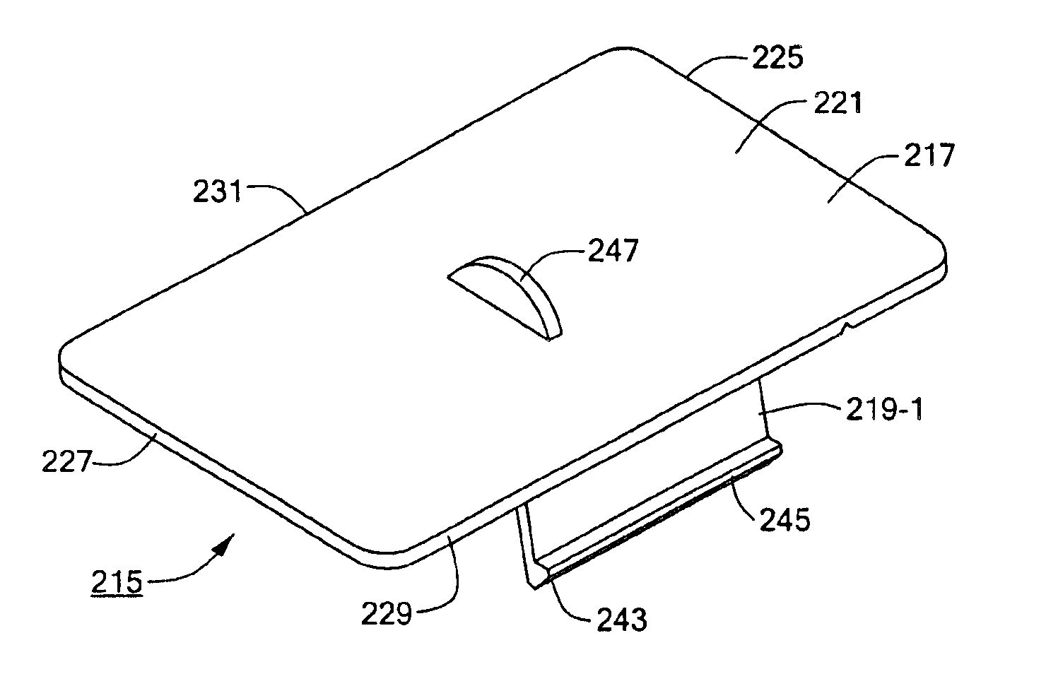
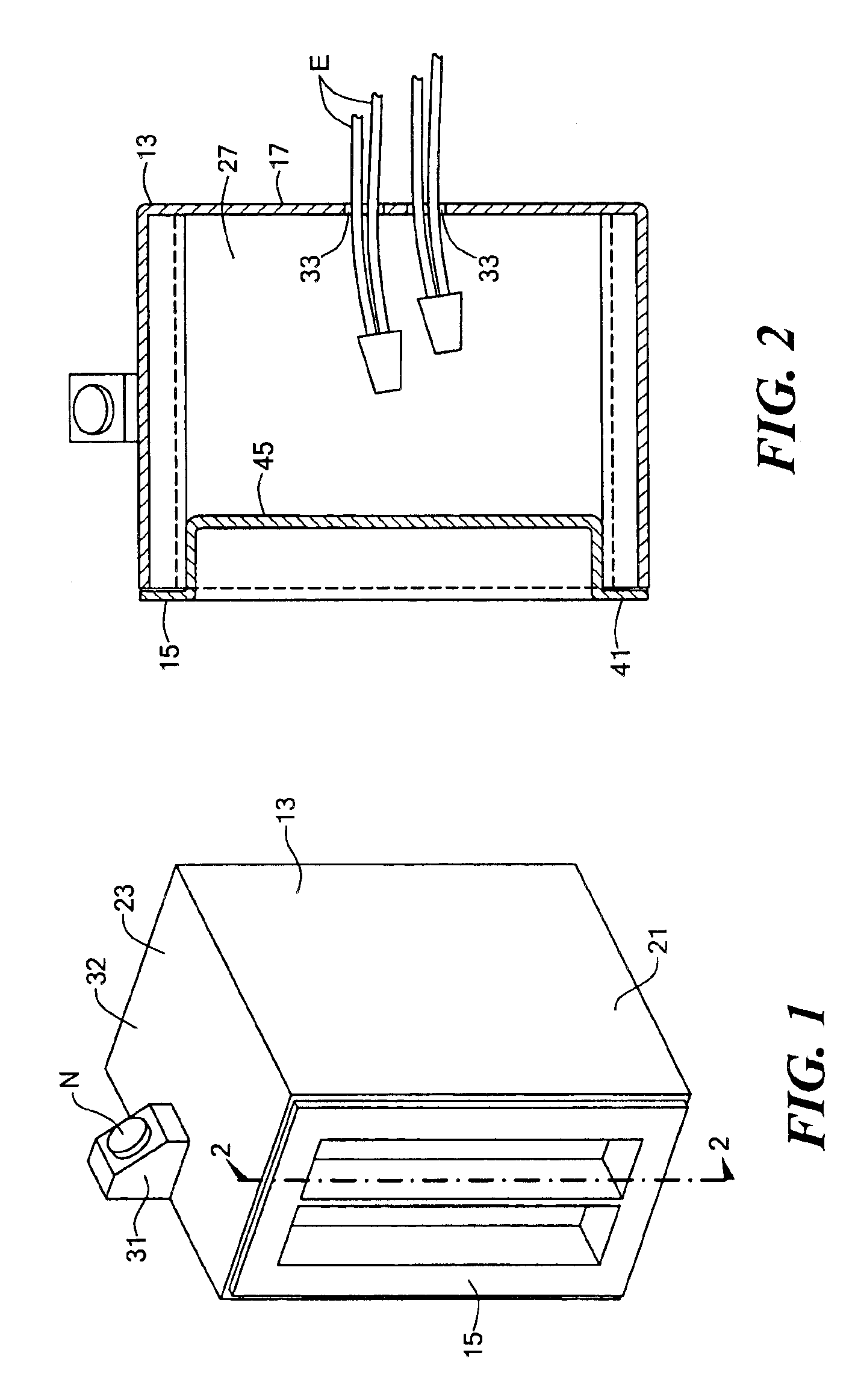
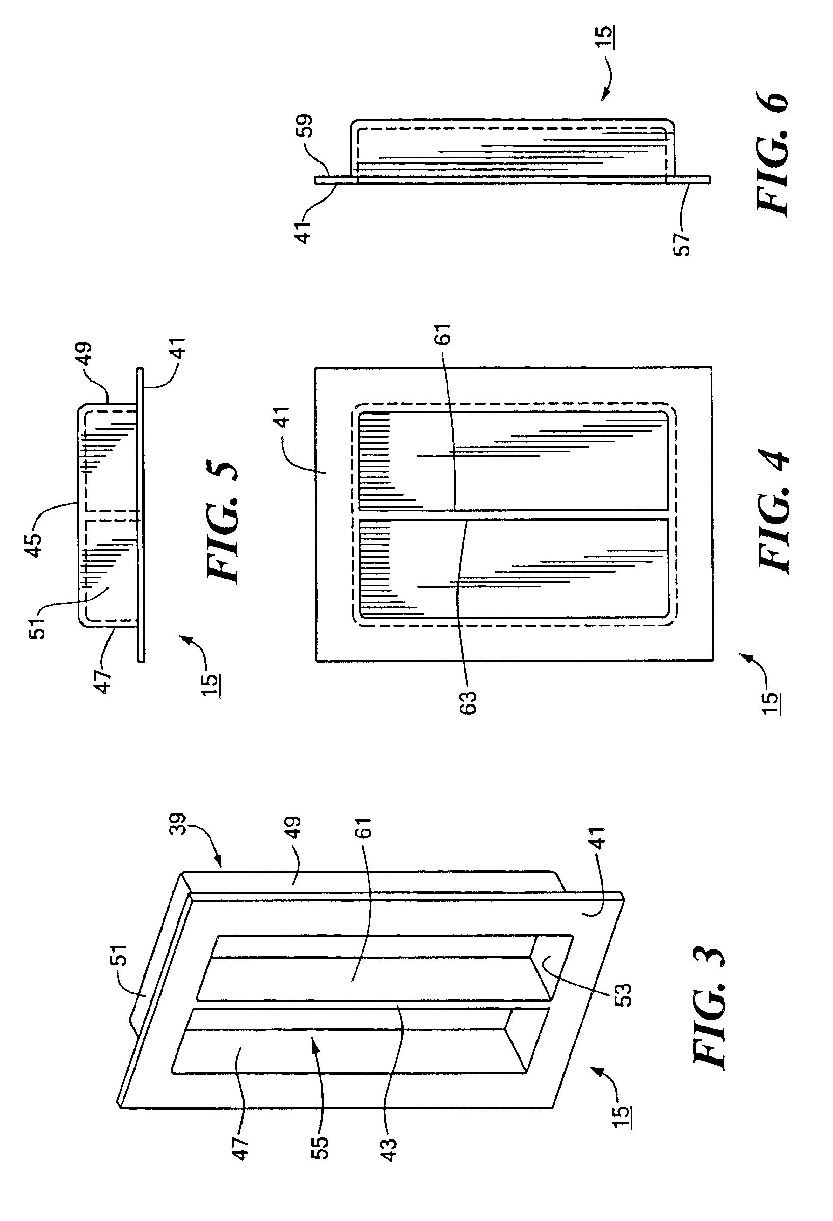
Referring now to FIG. 1, there is shown a cover which is adapted to be removably mounted onto an electrical box, said cover being constructed according to the teachings of the present invention. For purposes of identification, the electrical box is represented generally by reference numeral 13 and the cover is represented generally by reference numeral 15.

As will be described further in detail below, electrical box 13 serves two principal functions. First, electrical box 13 serves as a mounting structure for installing an electrical device, such as an outlet, switch or fixture, into a covering, such as a wall or ceiling panel. Second, electrical box 13 serves as a connection point for coupling the electrical device to electrical wires which, in turn, are connected to a main power source.

Electrical box 13 is a conventional new-work, electrical wall box which is constructed out of a nonmetallic material, such as plastic. Electrical box 13 is represented herein as a single gang electri...

second embodiment

As an example, referring now to FIG. 12, there is disclosed a cover which is adapted to be removably mounted onto an electrical box, said cover being constructed according to the teachings of the present invention. For purposes of identification, the electrical box is represented generally by reference numeral 73 and the cover is represented generally by reference numeral 75.

Electrical box 73 is a conventional new-work, electrical wall box which differs from electrical box 13 only in that electrical box 73 is a three gang electrical box (i.e., designed to be used as a mounting structure for three electrical devices), whereas electrical box 13 is a single gang electrical box (i.e., designed to be used as a mounting structure for a single electrical device). Accordingly, cover 75 differs from cover 15 in that cover 75 is substantially larger than cover 15. Specifically, cover 75 is sized and shaped to be removably mounted onto electrical box 73, which is considerably larger than elect...

third embodiment

As another example, referring now to FIG. 13, there is disclosed a cover which is adapted to be removably mounted onto an electrical box, said cover being constructed according to the teachings of the present invention. For purposes of identification, the electrical box is represented generally by reference numeral 83 and the cover is represented generally by reference numeral 85.

Electrical box 83 is a conventional new-work, electrical box which differs from electrical box 13 only in that electrical box 83 is designed to be used as a ceiling box, whereas electrical box 13 is designed to be used as a wall box. As such, electrical box 83 preferably has a generally circular shape and comprises a circular back panel 87 and a single circular side panel 89 which extends orthogonally out from back panel 87. Accordingly, cover 85 differs from cover 15 in that cover 85 is generally circular in shape so as to enable cover 85 to be removably mounted onto electrical box 83.


PUM


Abstract

A temporary protective cover for an electrical box having an open front end includes in one embodiment a plate shaped to enclose the open front end and a pair of wings formed onto the plate for securing the cover onto the electrical box. A line of weakness extends across the rear surface of the plate from the right side edge to the left side edge. A plurality of pins are formed onto the rear surface of the plate and serve to limit longitudinal and lateral movement of the cover when mounted onto the electrical box. The pair of wings are spaced adequately in from the left and right side edges of the plate and extend rearwardly from the rear surface of the plate at an angle away from one another. Each wing is shaped to include a flexible leg and an enlarged foot, the foot including a tapered guiding surface and a substantially flat engagement surface.

Description

BACKGROUND OF THE INVENTIONThe present invention relates generally to electrical wiring and, more particularly, to electrical boxes for electrical wiring.Electrical boxes are well known in the art and are commonly used to perform two principal functions. First, an electrical box commonly serves as a mounting structure for installing an electrical device, such as an outlet, switch or fixture, into a covering, such as a wall or ceiling panel. Second, an electrical box commonly serves as a connection point for coupling the electrical device to electrical wires which, in turn, are connected to a main power source.Electrical boxes are commonly manufactured in various shapes and sizes. The particular size and shape of an electrical box is based largely upon the particular application in which the box is to be used. Specifically, different types of electrical boxes are constructed according to the location in which the electrical box is to be installed. For example, a wall box is one well ...

Claims


Application Information

Patent Timeline
IPC IPC(8): H02G3/12
CPCH02G3/14H02G3/12
Inventor COMPAGNONE, JR., CARLO
Owner COMPAGNONE JR CARLO
Why Eureka
Try Eureka