Method of driving plasma display device and plasma display device

a plasma display device and plasma technology, applied in the direction of instruments, static indicating devices, etc., can solve the problems of degrading the drive margin or display quality of the pdp, and the inability to accurately select the cells to be turned on in accordance with display data, so as to achieve accurate selection

Inactive Publication Date: 2005-03-15
HITACHI LTD
View PDF12 Cites 15 Cited by
  • Summary
  • Abstract
  • Description
  • Claims
  • Application Information

AI Technical Summary

Benefits of technology

Since the present invention comprises the above technique, when the wall charges formed by sustain discharge between the sustain discharge electrodes are removed, a cell to be turned on in accordance with display data can be accurately selected without any influence of the wall charges remaining due to sustain discharge.

Problems solved by technology

That is, when wall charges remain on the address electrode after the end of the sustain discharge period, in selecting (addressing) a cell to be turned on in the address period, the cell to be turned on cannot be accurately selected in accordance with display data.
This degrades the drive margin or display quality of the PDP.

Method used


Image

  • Method of driving plasma display device and plasma display device
  • Method of driving plasma display device and plasma display device
  • Method of driving plasma display device and plasma display device

Examples


first embodiment

(First Embodiment)

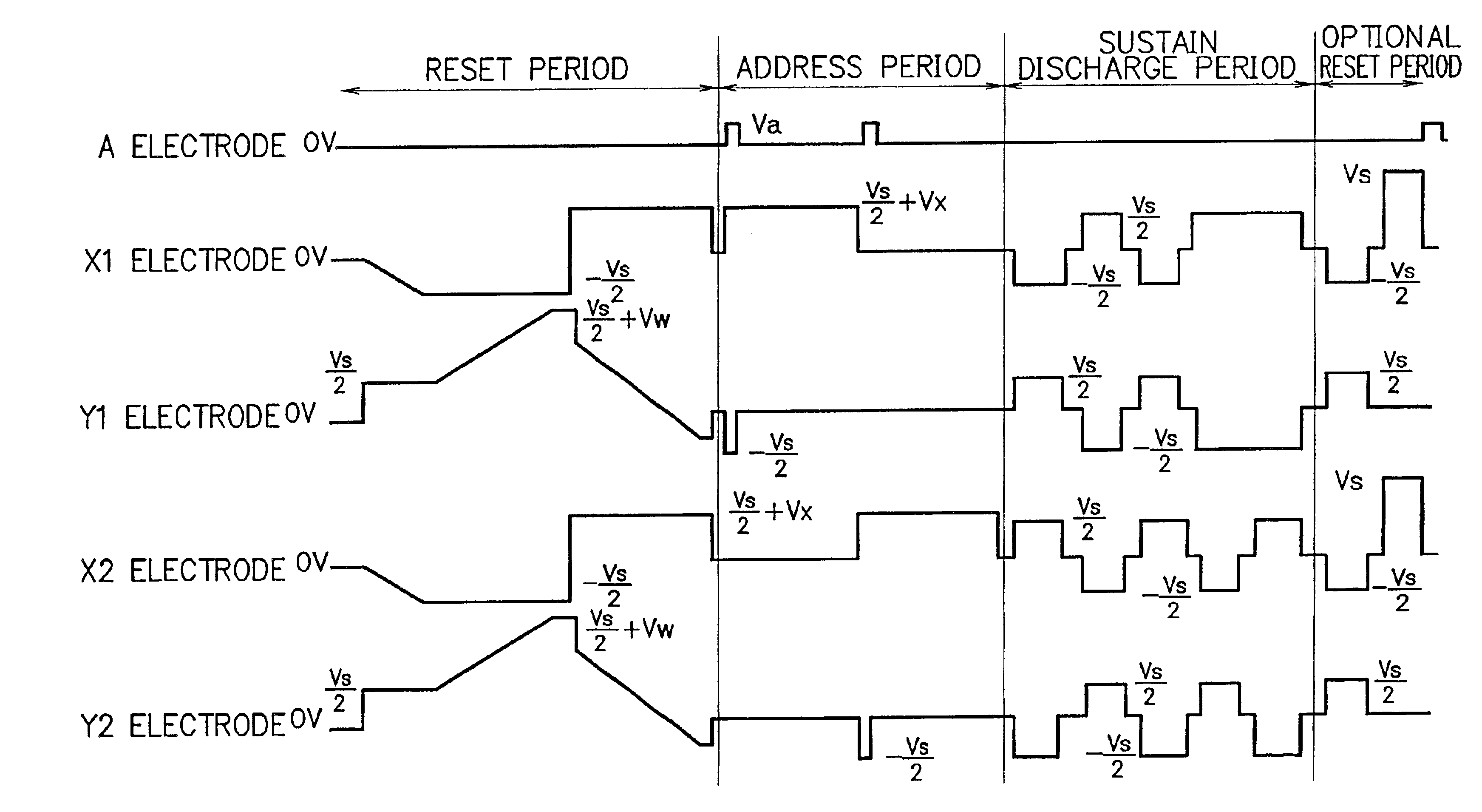
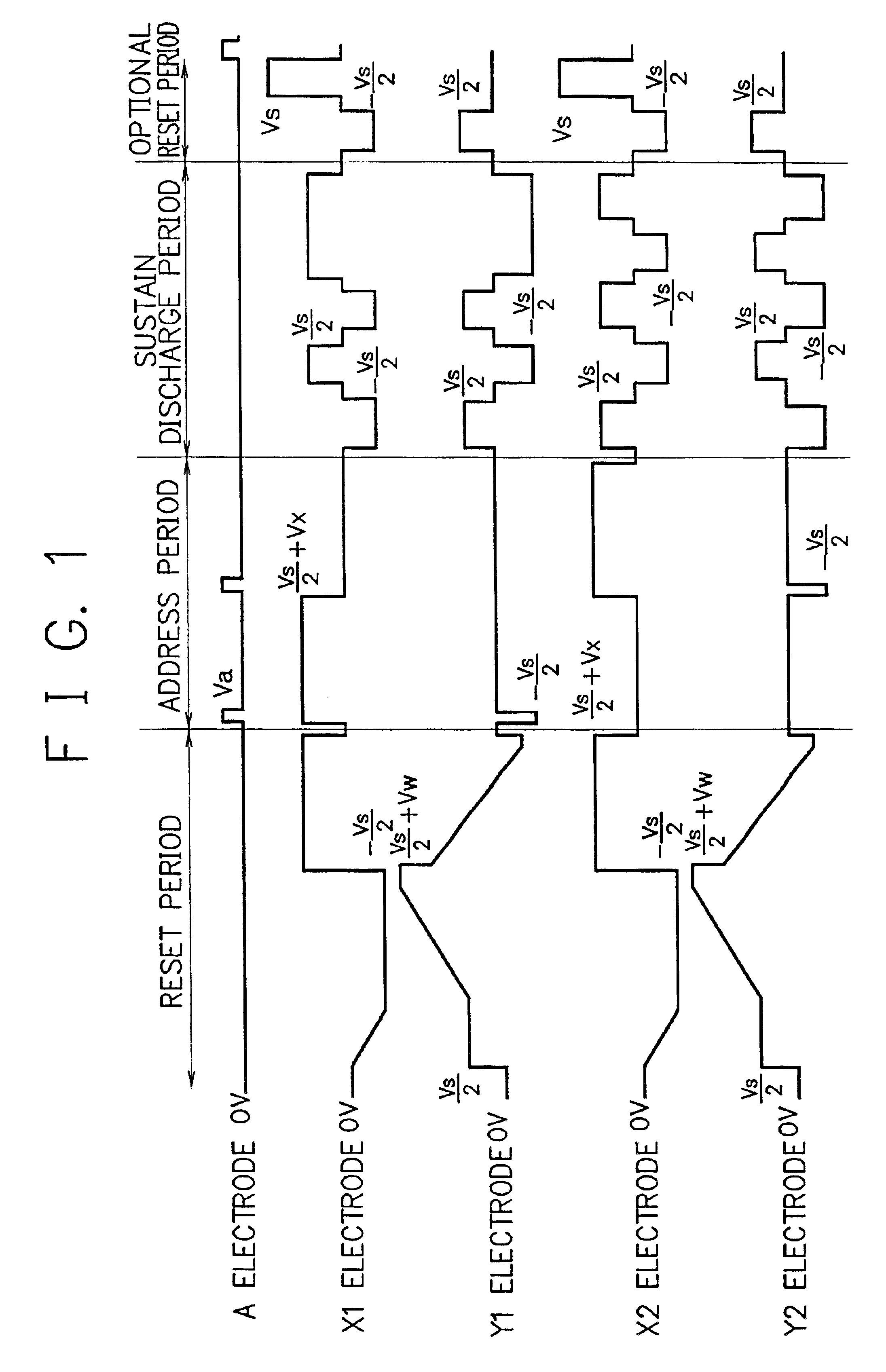
FIG. 1 is a timing chart showing an example of the drive waveforms of an AC-driven PDP according to the first embodiment.

FIG. 1 shows drive waveforms in the first field where discharge is performed between an X-electrode Xi and a Y-electrode Yi (i is an arbitrary integer) to display an image and, more specifically, drive waveforms in one of a plurality of subfields of the first field. One subfield is divided into a reset period comprised of a full write period and full erase period, an address period, a sustain discharge period, and an optional reset period.

In the reset period, first, a voltage (−Vs / 2) is applied to the X-electrodes X1 and X2. A voltage Vs / 2 is applied to the Y-electrodes Y1 and Y2, and then a ramp wave with a voltage (Vs / 2+Vw) is applied to the Y-electrodes Y1 and Y2. With this operation, discharge occurs in all cells of all display lines to form wall charges independently of the preceding display state (full write). When such a ramp wave is appli...

second embodiment

(Second Embodiment)

The second embodiment of the present invention will be described next.

FIG. 7 is a timing chart showing an example of the drive waveforms of an AC-driven PDP according to the second embodiment. In the timing chart of the drive waveforms of the second embodiment, a voltage Vs twice the sustain pulse voltage is applied to both X-electrodes and Y-electrodes at different timings in the optional reset period, unlike the first embodiment in which the voltage Vs twice the sustain pulse voltage is applied to the X-electrode or Y-electrode.

FIG. 7 shows drive waveforms in the first field and, more specifically, drive waveforms in one of a plurality of subfields of the first field. One subfield is divided into a reset period comprised of a full write period and full erase period, an address period, a sustain discharge period, and an optional reset period.

The drive waveforms in the reset period, address period, and sustain discharge period in FIG. 7 are the same as those shown...

third embodiment

(Third Embodiment)

FIG. 9 is a timing chart showing an example of the drive waveforms of the AC-driven PDP according to the third embodiment. In the timing chart of the drive waveforms shown in FIG. 9, the sustain pulse to be applied at the end of the sustain discharge period is replaced with a twice voltage Vs and applied to sustain discharge electrodes, unlike the first embodiment in which the voltage Vs twice the sustain pulse voltage is applied to the X-electrode or Y-electrode in the optional reset period.

FIG. 9 shows drive waveforms in the first field and, more specifically, drive waveforms in one of a plurality of subfields of the first field. One subfield is divided into a reset period comprised of a full write period and full erase period, an address period, and a sustain discharge period.

The drive waveforms in the reset period and address period in FIG. 9 are the same as those shown in FIG. 1, and a repetitive description will be omitted.

In the sustain discharge period, a p...


PUM


Abstract

After a sustain discharge period, a voltage twice a sustain pulse is applied to one of sustain discharge electrodes to form, on an address electrode, wall charges capable of self-erase discharge between an address electrode and the sustain discharge electrode by an address pulse, and the address pulse is applied to the address electrode to perform self-erase discharge between the address electrode and the sustain discharge electrode, thereby removing the wall charges formed on the address electrode. With this arrangement, a cell to be turned on in accordance with display data can be accurately selected in an address period without forming any wall charges on the address electrode, and any degradation in drive margin or display quality of a plasma display device can be suppressed.

Description

CROSS-REFERENCE TO RELATED APPLICATIONSThis application is based upon and claims priority of Japanese Patent Application No. 2001-12417, filed on Jan. 19, 2001, the contents being incorporated herein by reference.BACKGROUND OF THE INVENTION1. Field of the InventionThe present invention relates to a method of driving a plasma display device and a plasma display device and, more particularly, to a method of driving a three-electrode surface-discharge plasma display device.2. Description of the Related ArtAC-driven plasma display panels (PDPs) have conventionally received a great deal of attention as next-generation displays replacing CRTs because the PDPs are self-emission-type displays excellent in visibility and they also allow display on large thin screens. Particularly, surface-discharge PDPs are expected as displays compatible with high-definition digital broadcasting due to their larger screen size and are required to have an image quality higher than CRTs.AC-driven PDPs are cla...

Claims


Application Information

Patent Timeline
Patent Type & Authority Patents(United States)
IPC IPC(8): G09G3/28G09G3/288G09G3/291G09G3/20G09G3/292G09G3/294G09G3/296G09G3/298G09G3/299
CPCG09G3/2927G09G3/294G09G3/299G09G2320/0228G09G2310/066G09G3/296
Inventor TAKAMORI, TAKAHIROSETOGUCHI, NORIAKIITO, EIJIKISHI, TOMOKATSU
Owner HITACHI LTD
Why Eureka
Try Eureka