Digital television broadcast signal receiver

a digital television and receiver technology, applied in the direction of receiving monitoring, transmission monitoring, television systems, etc., can solve the problems of affecting the image quality of the receiver, and changing the reception condition frequently, so as to achieve less interference and improve the image quality

a digital television and receiver technology, applied in the direction of receiving monitoring, transmission monitoring, television systems, etc., can solve the problems of affecting the image quality of the receiver, and changing the reception condition frequently, so as to achieve less interference and improve the image quality

US20060020978A1Inactive Publication Date: 2006-01-26FUNAI ELECTRIC CO LTD

Image

  • Digital television broadcast signal receiver
  • Digital television broadcast signal receiver
  • Digital television broadcast signal receiver

Examples


Embodiment Construction

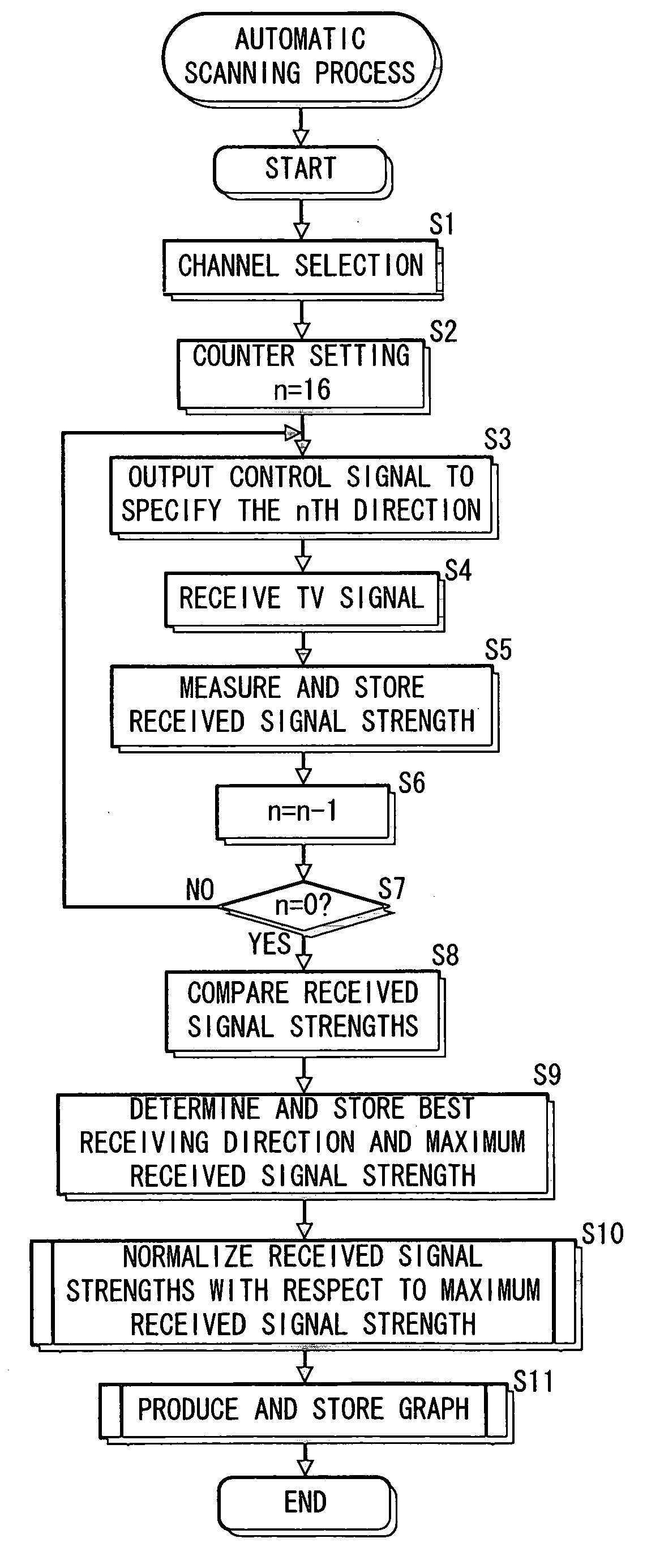
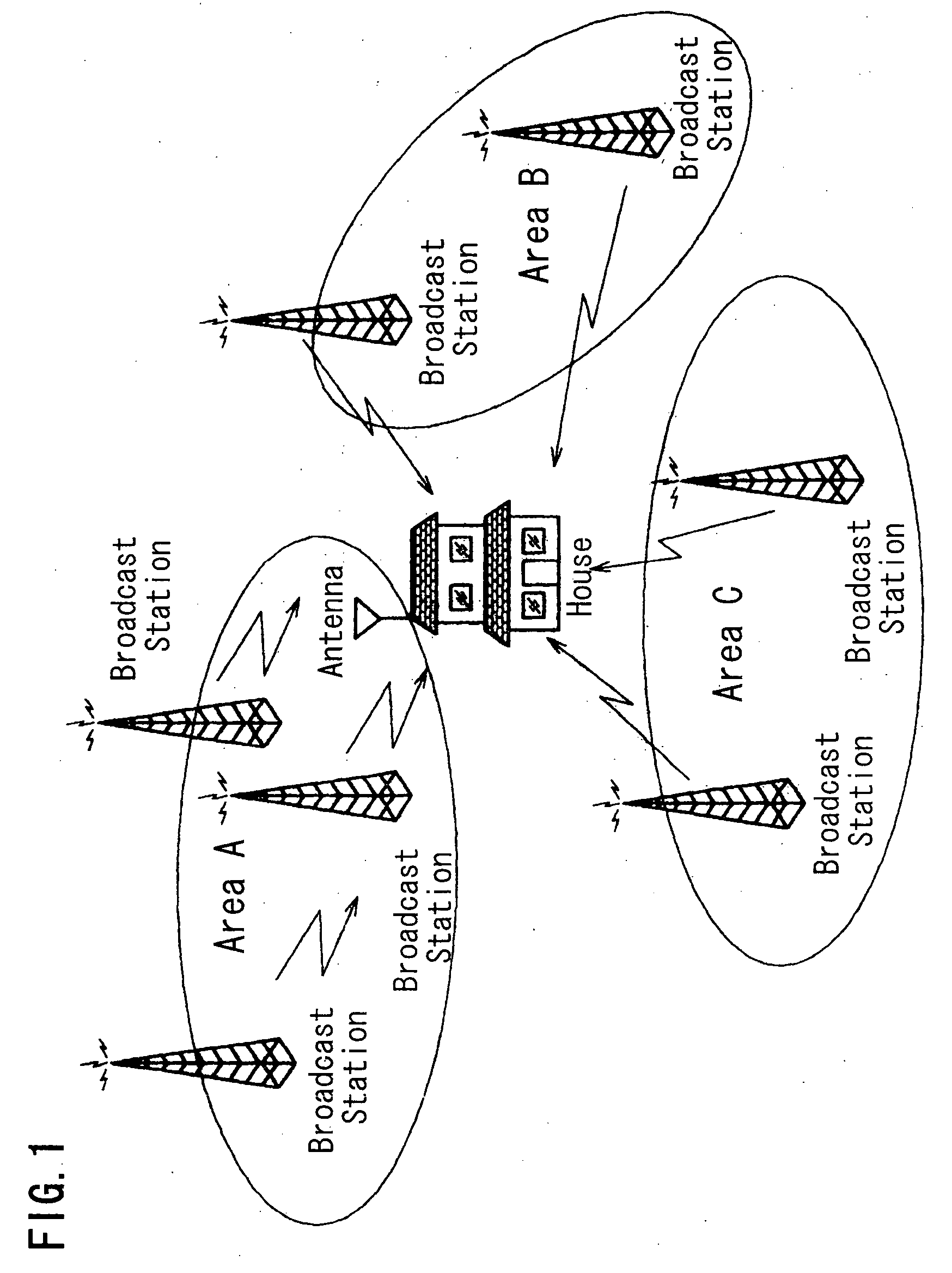
[0033] Referring now to the accompanying drawings, a digital TV broadcast signal receiver embodying the present invention is described. FIG. 1 shows a situation in which a user receives TV signals at home. In an area where digital (terrestrial) TV broadcast is provided, images of a certain quality can be obtained through error correction and the like as long as the strength of a received digital TV signal is equal to or higher than a predetermined threshold value. Accordingly, as shown in FIG. 1, it is possible for a user to receive TV signals transmitted from broadcast stations located at multiple areas, e.g., area A, area B, and area C so as to view TV programs provided by the broadcast stations. For this situation, a multi-directional antenna having multiple receiving directions, which is called a smart antenna, is in practical use.

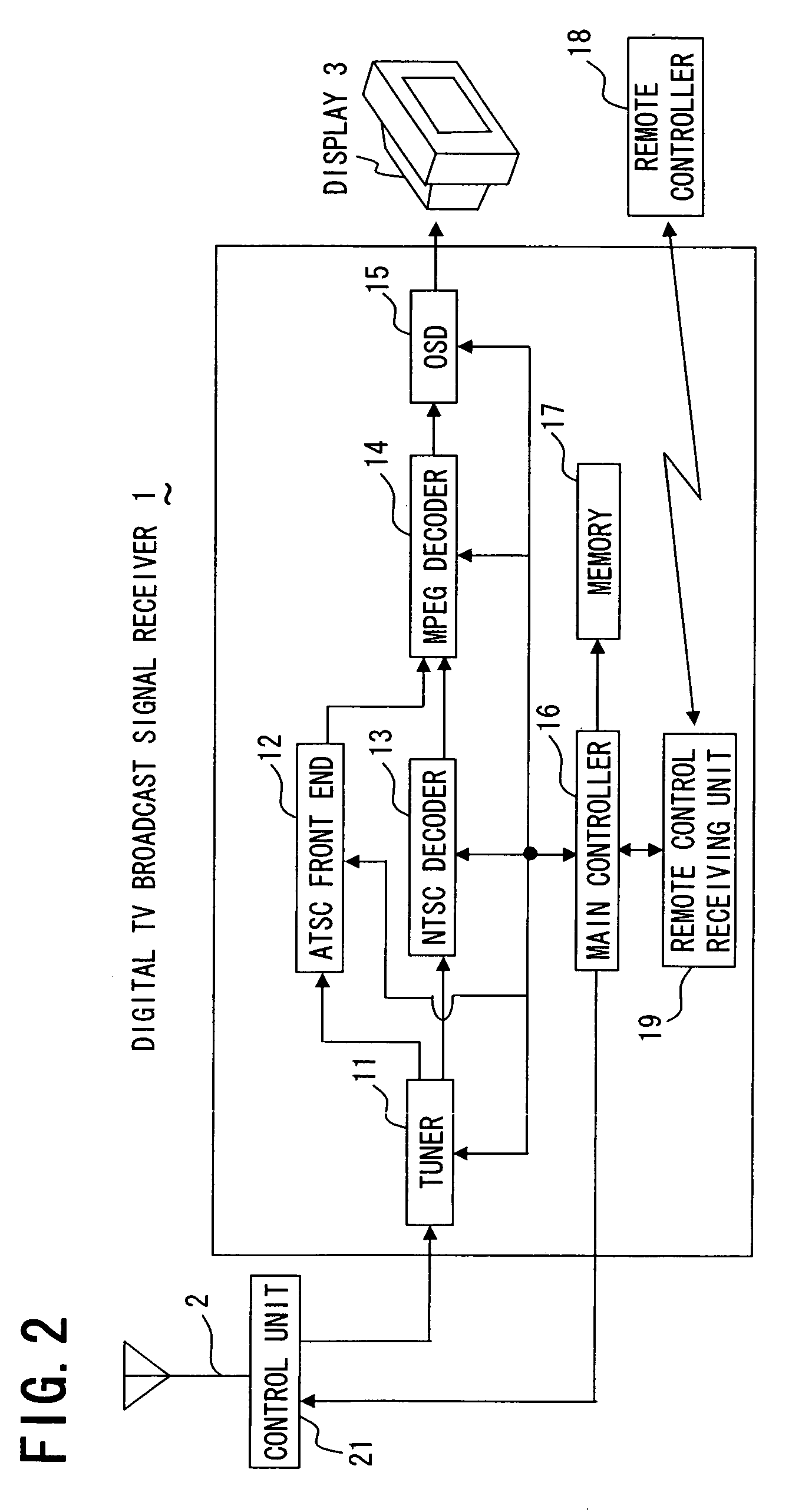
[0034] A digital TV broadcast signal receiver can receive not only digital TV signals but also analog TV signals. When receiving either digital or an...


PUM


Abstract

A digital television broadcast signal receiver connected to a multi-directional antenna carries out in advance automatic scanning for each channel to determine and store the strength of a signal received in each of multiple receiving directions of the antenna, a best receiving direction, and a maximum value of the received signal strengths, normalize the received signal strengths measured in the respective directions with respect to the maximum received signal strength, and produce and store an antenna direction level pattern including a bar graph that shows the received signal strengths in the respective directions with the normalized values used as the amplitude. In response to a command from a user, the receiver superimposes the level pattern on a video image being received for display on a display screen, so that a user can select a receiving direction on the screen. When image degradation takes place during signal reception by the antenna having been already adjusted in orientation, a user can manually reorient the antenna so as to quickly improve the receiving condition without the need for additional time-consuming automatic scanning for adjustment of the orientation of the antenna.

Description

BACKGROUND OF THE INVENTION [0001] 1. Field of the Invention [0002] The present invention relates to a digital television broadcast signal receiver for receiving a digital television signal such as an Advanced Television Systems Committee (ATSC) signal. [0003] 2. Description of the Related Art [0004] In the North America where ATSC digital television broadcast (hereinafter referred to as TV broadcast) is provided, television signals are transmitted from variously located broadcast stations at big cities or their suburbs in the plains. From the viewpoint of a user who receives such TV broadcast, television signals come from various directions. Accordingly, it is necessary for a user to adjust the orientation of an antenna so as to aim the antenna at a broadcast station transmitting a desired TV program. For this purpose, multi-directional antennas such as smart antennas are put into practical use. [0005] The Electronic Industries Association (EIA)-909 standard provides that a smart a...

Claims


Application Information

Patent Timeline
26 Jan 2006
Publication
US20060020978A1
IPC
H04N7/20; H04B1/16; H04N5/44; H04N5/445; H04N5/45
CPC
H04N5/4401; H04N21/42204; H04N21/4316; H04N21/485; H04N21/440263; H04N21/44209; H04N21/4383; H04N21/426
Inventors
MIYAGAWA, TATSUO