Cleaning device and image forming apparatus using the same

a cleaning device and image forming technology, applied in the direction of vehicle cleaning, instruments, manufacturing tools, etc., can solve the problems of defective cleaning, inability to adequately remove residual toner, and inability to clean defective images

Inactive Publication Date: 2005-03-15
RICOH KK
View PDF34 Cites 11 Cited by
  • Summary
  • Abstract
  • Description
  • Claims
  • Application Information

AI Technical Summary

Benefits of technology

It is therefore an object of the present invention to provide a cleaning device capable of surely removing additives separated from toner and sheets from an image carrier to thereby obviate defective images, and an image forming apparatus using the same.

Problems solved by technology

Such toner, however, is apt to bring about defective cleaning, as will be described hereinafter.
This type of cleaning device, however, cannot adequately remove the residual toner and makes images defective when use is made of toner with a small grain size for the following reasons.
Although such additives each are effective for a particular purpose, they are separated from the toner and sheets due to repeated image formation and deposit on the image carrier.
It is difficult for the cleaning blade to fully remove the additives, which are fine grains, so that toner with a small grain size accumulates on the surface of the image carrier little by little.
This part of the toner is blocked by the fine grains of additives and cannot be easily scraped off despite the action of the cleaning blade.
Consequently, stains intermittently appear on the background or the white portion of an image and therefore appear in the resulting toner image in the form of a black stripe, making the toner image defective.
Another problem with toner with a small grain size is that the amount of charge to deposit on the individual toner grain increases, increasing adhesion acting between the toner and the image carrier.
This makes it difficult for the cleaning blade to block the toner grains and thereby causes the toner grains moved away from the cleaning blade to form black stripes in the background of an image.

Method used


Image

  • Cleaning device and image forming apparatus using the same
  • Cleaning device and image forming apparatus using the same
  • Cleaning device and image forming apparatus using the same

Examples


Embodiment Construction

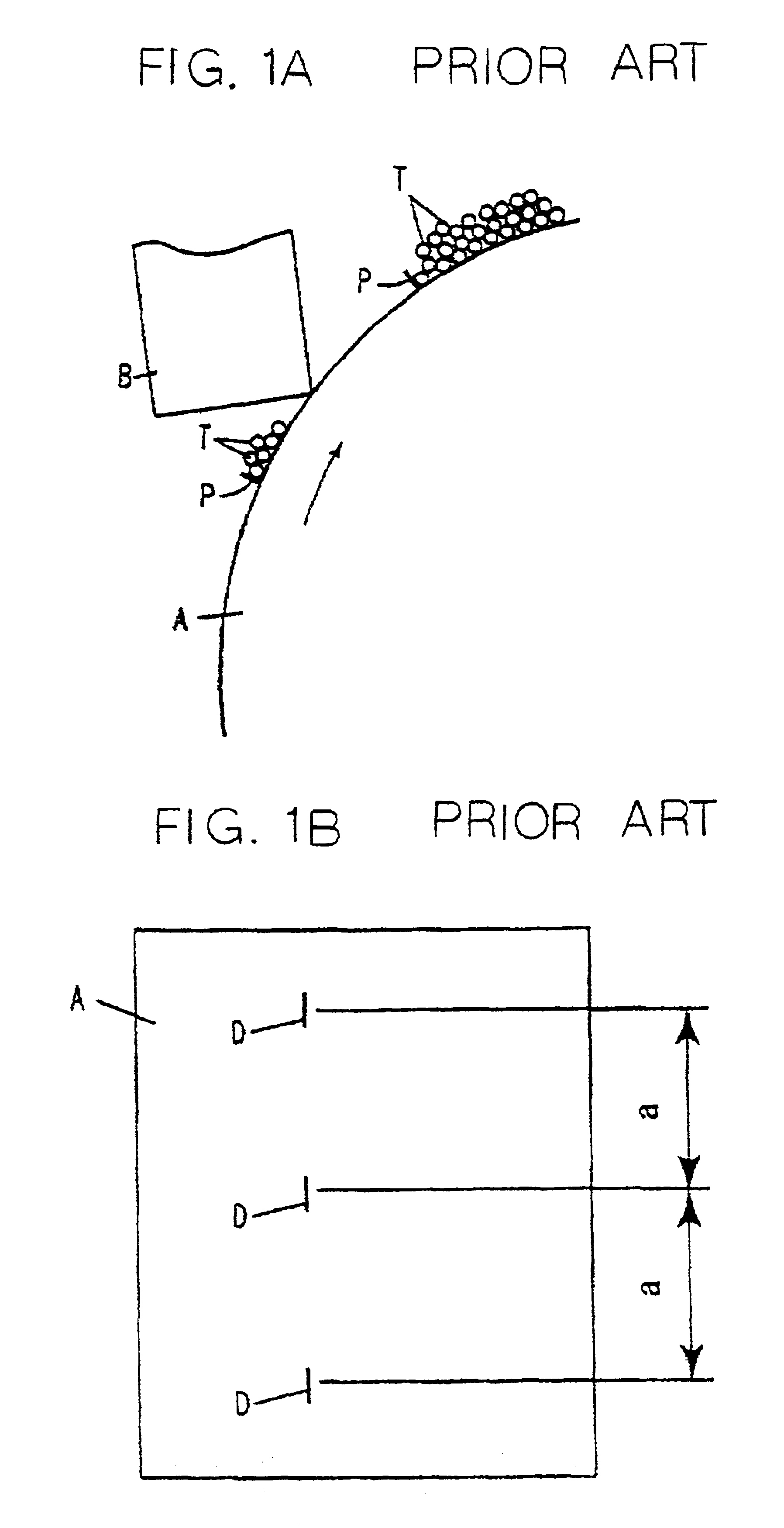
To better understand the present invention, the problem with the conventional cleaning system of the type using a cleaning blade will be described more specifically. A cleaning blade pressed against a photoconductive element cannot sufficiently remove toner having a small grain size and makes images defective, as stated earlier. This is because various additives added to toner and sheets are too small in grain size to be fully removed by the cleaning blade.

More specifically, FIG. 1A shows a cleaning blade B held in contact with the surface of a photoconductive drum A. As shown, assume that the cleaning blade F fails to remove toner grains T from the drum A, and that fine grains P of additives are separated from the toner T and sheets. Then, toner grains T with a small grain size is apt to accumulate around the above toner T and fine grains P. The toner grains accumulated are blocked by the fine grains P and cannot be fully scraped off despite the action of the cleaning blade B.

Toner...


PUM

PropertyMeasurementUnit
grain sizeaaaaaaaaaa
electric resistanceaaaaaaaaaa

Abstract

In an image forming apparatus, after the development of a latent image formed on an image carrier effected by using toner, which has a volume mean grain size of 5 μm to 10 μm and in which 60 number percent to 80 number percent of toner grains have a grain size of 5 μm or below, and the transfer of the resulting image to a recording medium, a cleaning device of the present invention removes the toner left on the image carrier with a fur brush. The fur brush is capable of contacting the surface of the image carrier with density high enough to block the toner grains having the above grain size.

Description

BACKGROUND OF THE INVENTION1. Field of the InventionThe present invention relates to a cleaning device and an image forming apparatus using the same and more particularly to a structure for cleaning an image carrier included in an image forming apparatus.2. Description of the Background ArtAn electrophotographic process is one of conventional processes available for forming an image corresponding to a document or image information and disclosed in, e.g., U.S. Pat. No. 2,297,091 and Japanese Patent Publication Nos. 49-23910 and 43-24748. It is a common practice with the electrophotographic process to use an image carrier having a photoconductive layer. The photoconductive layer is exposed imagewise or scanned by a light beam to form a latent image representative of a document or image information. In the case of development using dry toner, the latent image is developed by the dry toner to become a toner image. The toner image is transferred to a sheet or recording medium and then fi...

Claims


Application Information

Patent Timeline
Patent Type & Authority Patents(United States)
IPC IPC(8): G03G21/00G03G9/08G03G21/10
CPCG03G21/0035
Inventor AKIBA, YASUSHI
Owner RICOH KK
Why Eureka
Try Eureka