Variable power steering assist using driver grip pressure

a technology of driver grip and assistive steering, which is applied in the direction of steering initiation, instruments, vessel construction, etc., can solve the problems of a driver being particularly difficult to turn

Inactive Publication Date: 2005-03-22
HONDA MOTOR CO LTD
View PDF19 Cites 43 Cited by
  • Summary
  • Abstract
  • Description
  • Claims
  • Application Information

AI Technical Summary

Problems solved by technology

Power-assist steering is desirable when the vehicle is moving slowly over a high-friction surface, such as concrete, because the steering wheel of such a vehicle can be especially difficult for a driver to turn under such conditions.

Method used


Image

  • Variable power steering assist using driver grip pressure
  • Variable power steering assist using driver grip pressure

Examples


Embodiment Construction

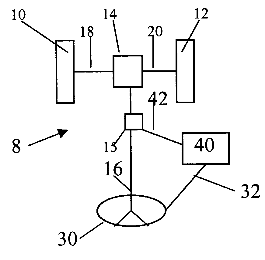
The preferred embodiment of the present invention is shown in FIG. 1 in schematic form. The steerable wheels 10 and 12 of a vehicle, preferably the front wheels of an automobile 8, are mounted to a gear mechanism 14. The steerable wheels and preferably two other wheels rest upon the ground beneath the vehicle in a conventional manner. In a preferred embodiment, the steerable wheels of the automobile 8 are conventional tires mounted on rims and resting upon pavement.

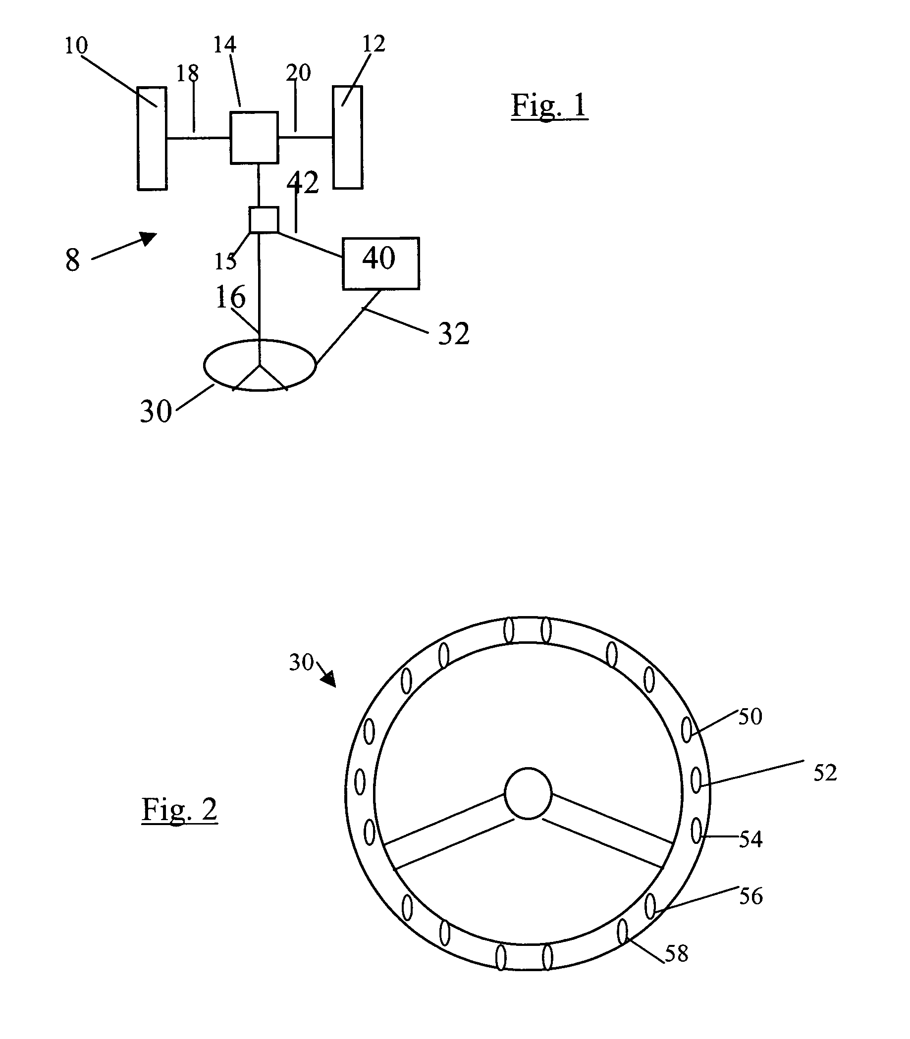
The gear mechanism 14 is preferably a conventional rack and pinion mechanism or other equivalent apparatus that translates the rotational motion of the steering shaft 16 into longitudinal motion of the steering linkage rods 18 and 20. The steering shaft 16 is rotated when the driver of the vehicle rotates the steering wheel 30, thereby causing the steerable wheels 10 and 12 to turn to one side or the other for steering the automobile 8. The rack and pinion mechanism is conventional for an automobile steering system, alth...


PUM


Abstract

A variable power assist apparatus for vehicles, such as automobiles. The apparatus includes a plurality of sensors, preferably electromechanical transducers, mounted to the hand-grippable region of a steering wheel. The sensors are connected to a computer that controls the power-assist device of the automobile, and produce a signal that is a function of grip pressure. The computer varies the amount of assist provided to the steering system as a function of at least the grip pressure.

Description

BACKGROUND OF THE INVENTION 1. Field of the Invention This invention relates generally to power steering apparatuses, and more particularly to a power steering apparatus that includes as an input the grip pressure a driver exerts on a steering wheel. 2. Description of the Related Art It is known to provide a mechanism to assist the driver of a vehicle, in particular an automobile, in the steering of the wheels of the vehicle. Power-assist steering is desirable when the vehicle is moving slowly over a high-friction surface, such as concrete, because the steering wheel of such a vehicle can be especially difficult for a driver to turn under such conditions. At higher driving speeds and under other conditions, it is desirable to have little or no assist in order to maintain the amount of feedback provided by the steering system to the driver. Thus, variable-assist power steering systems have been developed for providing a relatively high amount of power assist when desired, and for pro...

Claims


Application Information

Patent Timeline
Patent Type & Authority Patents(United States)
IPC IPC(8): B62D1/06B62D6/00
CPCB62D1/06B62D6/007B62D6/00
Inventor DIRRIG, JOHN ERNEST
Owner HONDA MOTOR CO LTD
Why Eureka
Try Eureka