Seatback frame for vehicle seat

a seatback frame and vehicle seat technology, applied in the direction of chairs, pedestrian/occupant safety arrangements, safety belts, etc., can solve the problems of difficult to adopt the active type headrest with an increased functional property and relatively unsatisfactory results, and achieve the effect of degrading operability and increasing weigh

Inactive Publication Date: 2005-03-22
JOHNSON CONTROLS AUTOMOTIVE SYSTEMS CORP
View PDF2 Cites 33 Cited by
  • Summary
  • Abstract
  • Description
  • Claims
  • Application Information

AI Technical Summary

Benefits of technology

In the seatback frame 1 for the vehicle seat equipped with the seat belt of the related art practice, the cross member 4 located so as to extend from the upper distal end of the tower frame 3 toward the opposing side portion of the seatback frame for reinforcement has an increased weight, providing a degraded operability during a reclining operation of the seatback.

Problems solved by technology

Further, the presence of the cross member 4 obliquely located in a substantially central area of the seatback so as to cross over the same encounters a difficulty in enhancing a space for locating an active-type headrest (which is of the type wherein when exerted with impact shocks, lower distal ends of the headrest stays are urged rearward to cause the headrest to move forward for thereby preventing the head of the seat occupant from being swayed rearward to protect the same).
As a result, only a general-purpose headrest can only be employed in the seatback, with a difficulty in adopting the active type headrest with an increased functional property.
However, with such a reinforced structure using the cross member 4, although a rigidity is provided in structure in a widthwise direction of a vehicle body, a relatively unsatisfied result takes place in the presence of the impact shocks imparted in the forward and rearward directions of the vehicle body.

Method used


Image

  • Seatback frame for vehicle seat
  • Seatback frame for vehicle seat
  • Seatback frame for vehicle seat

Examples


Embodiment Construction

To describe the present invention more in detail, a seatback frame of an embodiment of the present invention to be applied to a vehicle seat will be explained below in detail with reference to the drawings.

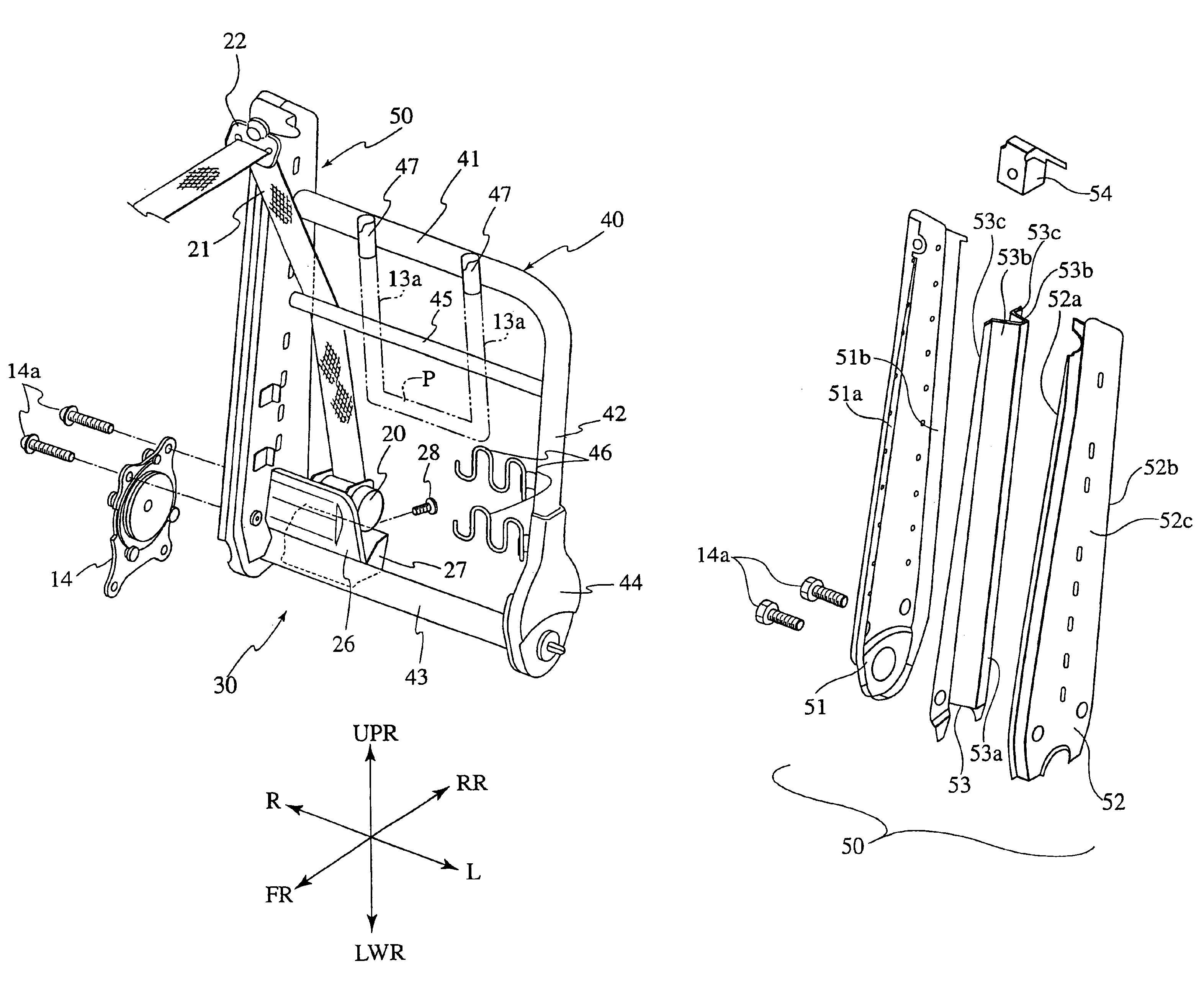
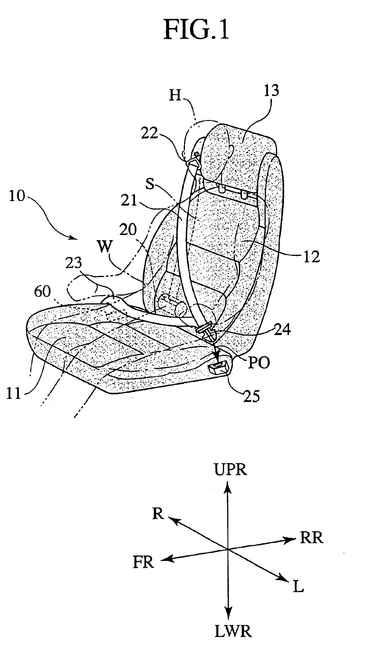
FIG. 1 is a perspective view of the vehicle seat employing the seatback frame according to the present invention. FIG. 2 is a perspective view illustrating a structure of the seatback according to the present invention. FIG. 3 is an exploded perspective view illustrating a structure of a tower frame which forms the seatback frame shown in FIG. 3. FIGS. 4A, 4B and 4C are cross sectional views illustrating the tower frame, shown in FIG. 3, in conjunction with associated component parts shown in FIG. 2. In the Figures, frontward and rearward directions of a vehicle body are respectively represented by arrows FR and RR, rightward and leftward directions of the vehicle body are respectively represented by arrows R and L, upward and downward directions of the vehicle body are respective...


PUM


Abstract

In a seatback frame for a vehicle seat having a seatback and a seat cushion and equipped with a seat belt of a three-point type, a pipe frame formed along an external shape of the seatback and a vertically extending tower frame located in the seatback at the same side as a belt-through member of the seat belt of the three-point type and fixedly connected to the pipe frame are provided. The tower frame includes an outer side bracket, an inner side bracket, both of which are formed of vertically extending, elongated metal sheets each formed in a substantially C-shaped cross section and both of which are coupled to one another in abutting engagement with one another to form an internal space, and an intermediate brace member incorporated in the internal space to provide a reinforcement rib structure.

Description

BACKGROUND OF THE INVENTIONThe present invention relates to a seatback frame for a vehicle seat and, more particularly, to a seatback frame for a vehicle seat equipped with a seat belt of the three-point type wherein a retractor for winding a seat belt is mounted at a lower portion of the seatback and allows a shoulder belt to be pulled out for restraining a seat occupant, a belt-through member is mounted at an upper distal end of the seatback for guiding the shoulder belt, fixture segments are mounted at both sides of a seat cushion for supporting both ends of a lap belt which restrains the waist of the seat occupant, and a distal end of the shoulder belt is supported with one of the fixture segments.In general, seat belts in practical use are divided into two types, a first type in which a retractor is fixedly mounted to a pillar of a vehicle body and a second type in which the retractor is directly fixed to a seatback frame. The seat belt in normal use is constructed of a lap bel...

Claims


Application Information

Patent Timeline
Patent Type & Authority Patents(United States)
IPC IPC(8): B60N2/68B60R22/26B60N2/22B60N2/90
CPCB60N2/682B60R22/26B60N2/688
Inventor MATSUNUMA, NORIYOSHI
Owner JOHNSON CONTROLS AUTOMOTIVE SYSTEMS CORP
Why Eureka
Try Eureka