Device for projection display

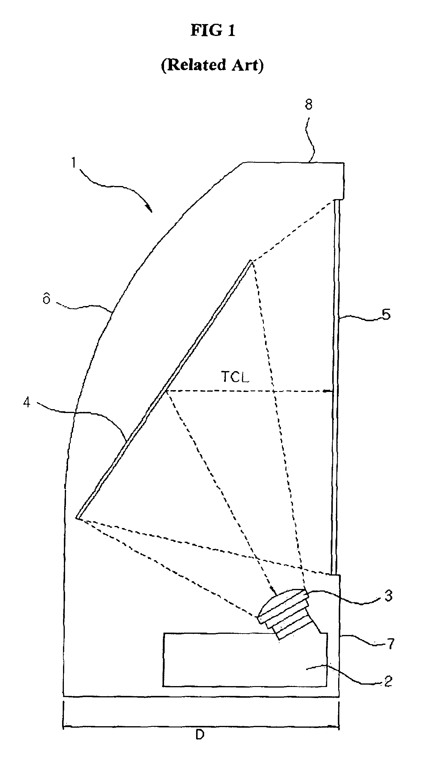
a projection display and display device technology, applied in the field of projection display devices, can solve the problems of the width of the display device b>1/b>, the length between the rear and the outer edge, and the surface of the screen b>5/b> becoming so long as the size of the screen b>5/b>, so as to achieve the effect of reducing the total width of the display devi

Inactive Publication Date: 2005-03-22
INTELLECTUAL DISCOVERY CO LTD
View PDF11 Cites 1 Cited by
  • Summary
  • Abstract
  • Description
  • Claims
  • Application Information

AI Technical Summary

Benefits of technology

[0023]The total width of the display device can be also reduced in a degree equal to the movement distance of the optical engine.

Problems solved by technology

As a result, because of the distance between the reflection mirror 4 and the screen 5, there is a problem that total width D of the display device 1, that is, the length between the rear of the outer case 6 and surface of the screen 5 becomes so longer than the size of the screen 5 that the compact configuration of the projection display device 1 can not be obtained.
In particular, although the projection display has high quality image and high resolution as compared with PDP TV or LCD TV, the thickness, that is, the total width of the display device becomes lengthened, thus resulting in some problems of the beauty of the device or space application.

Method used


Image

  • Device for projection display
  • Device for projection display
  • Device for projection display

Examples


Embodiment Construction

[0028]Hereinafter, the preferred embodiment of the present invention will be described with reference to the accompanying Figures.

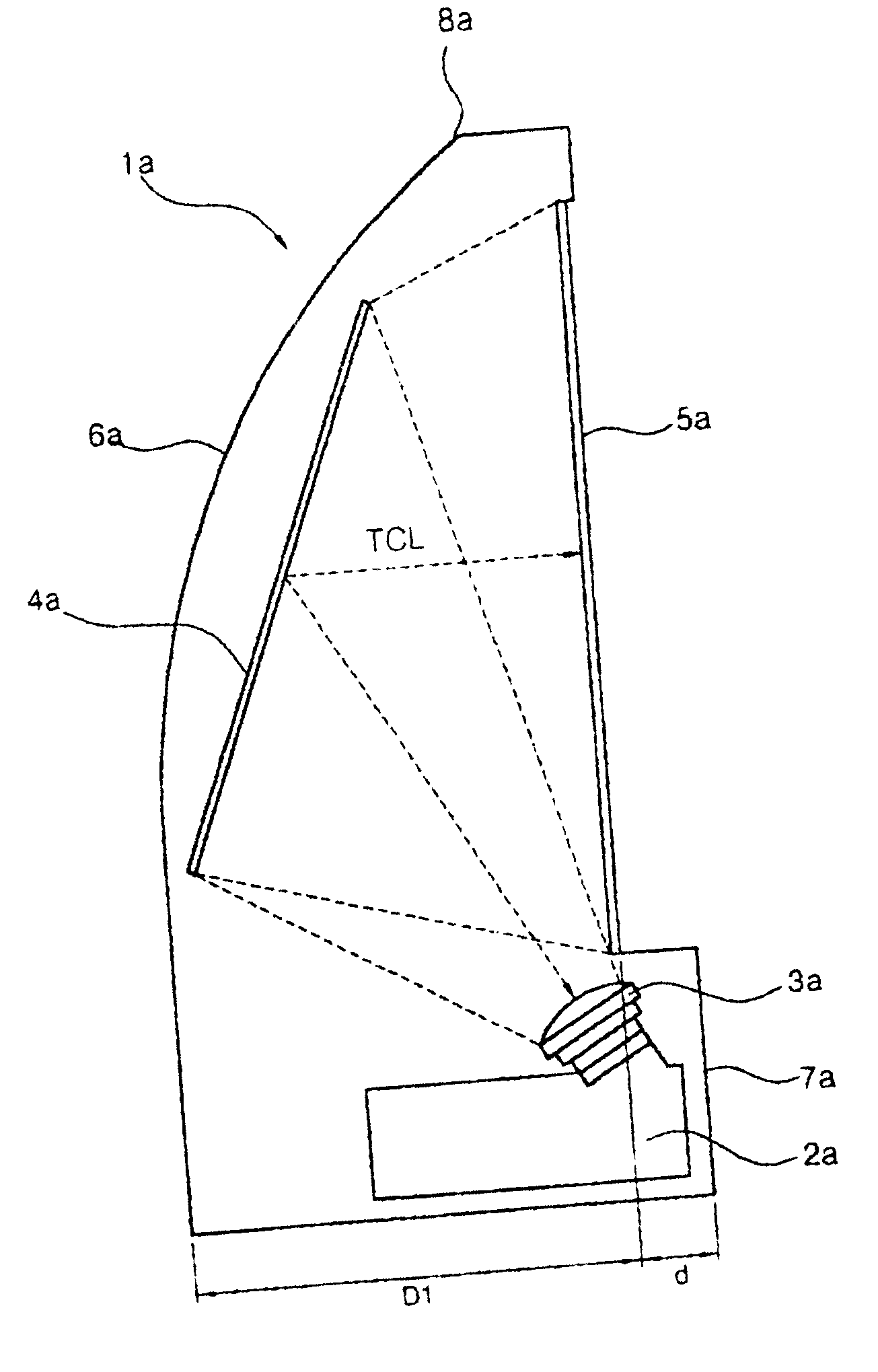
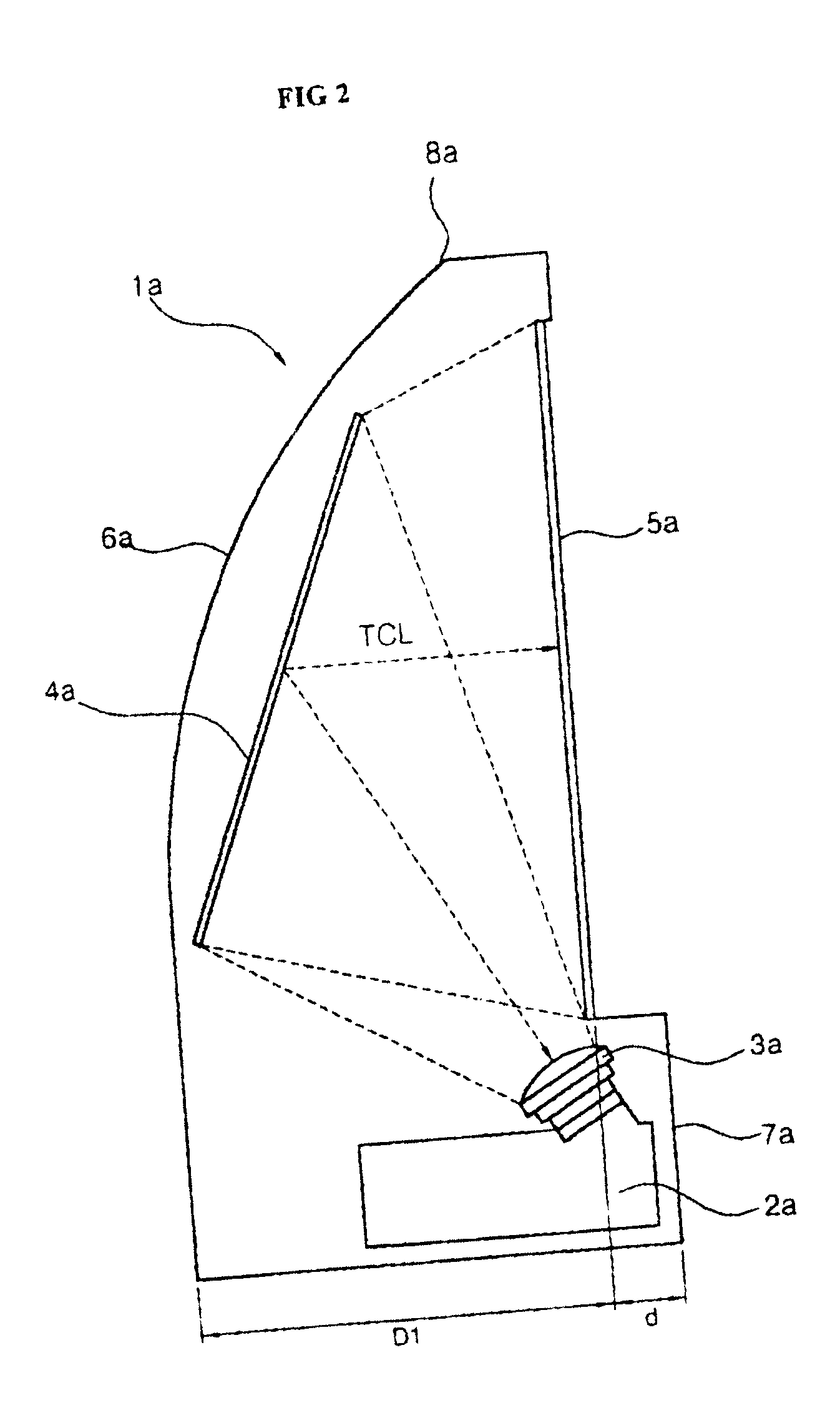
[0029]FIG. 2 is a cross-sectional view illustrating the configuration of the projection display device according to the present invention.

[0030]As shown in FIG. 2, the projection display device 1a according to the present invention comprises an optical engine 2a for projecting an electron beam, a projection lens 3a for magnifying and projecting the electron beam projected by the optical engine 2a, a reflection mirror 4a for reflecting the electron beam magnified and projected through the projection lens 3a on the full screen of a screen 5a, and the screen 5a for realizing an image using the electron beam reflected by the reflection mirror 4a. Here, 2a and 3a respectively designate the optical engine and the projection lens mounted with protrusion by a length d in front as compared with the screen 5a, 4a designates the reflection mirror mounted with an ang...


PUM


Abstract

A projection display device that is more compactly composed as compared with a conventional device by reducing the total width of a device, that is, the length between the rear of outer case and screen. The projection display device comprises an optical engine for projecting a light beam; a projection lens for magnifying and projecting the light beam projected by the optical engine; a reflection mirror for reflecting the light beam, magnified and projected through the projection lens, on the full screen of a screen; a screen for realizing an image using the light beam reflected by the reflection mirror; and a lower cabinet for supporting the screen, wherein a part of the optical engine mounted in the lower cabinet is protruded by a predetermined length in front as compared with the screen.

Description

BACKGROUND OF THE INVENTION[0002]1. Field of the Invention[0003]The present invention relates to a projection display device, and more particularly to a projection display device that is more compactly composed as compared with a conventional device by reducing the total width of a device, that is, the length between the rear of outer case and screen.[0004]2. Description of the Related Art[0005]Generally, a projection display device is a display system where a small image is implemented on a separate plane (screen) in a large screen by magnifying and projecting the small image through an optical lens (optical engine or projection lens).[0006]The configuration of a projection television (hereinafter, a display device) capable of implementing this system will be described in the following.[0007]FIG. 1 is a cross-sectional view illustrating the configuration of the conventional projection display device.[0008]As shown in FIG. 1, the projection display device 1 comprises an optical engi...

Claims


Application Information

Patent Timeline
Patent Type & Authority Patents(United States)
IPC IPC(8): G03B21/10H04N5/74
CPCG03B21/10H04N9/3141H04N5/74
Inventor CHA, YOUNG CHUELHWANG, KYONG SOO
Owner INTELLECTUAL DISCOVERY CO LTD
Why Eureka
Try Eureka