Cleaning chamber and method for a sugarcane chopper harvester

Active Publication Date: 2005-03-22
DEERE & CO
View PDF17 Cites 30 Cited by
  • Summary
  • Abstract
  • Description
  • Claims
  • Application Information

AI Technical Summary

Benefits of technology

According to the present invention, ther

Problems solved by technology

Once through the high-speed air area, an air speed is eventually encountered that is not sufficient enough to levitate the material, and no further cleaning is achieved until the material reaches the opposite side of the cleaning cham

Method used


Image

  • Cleaning chamber and method for a sugarcane chopper harvester
  • Cleaning chamber and method for a sugarcane chopper harvester
  • Cleaning chamber and method for a sugarcane chopper harvester

Examples


Example

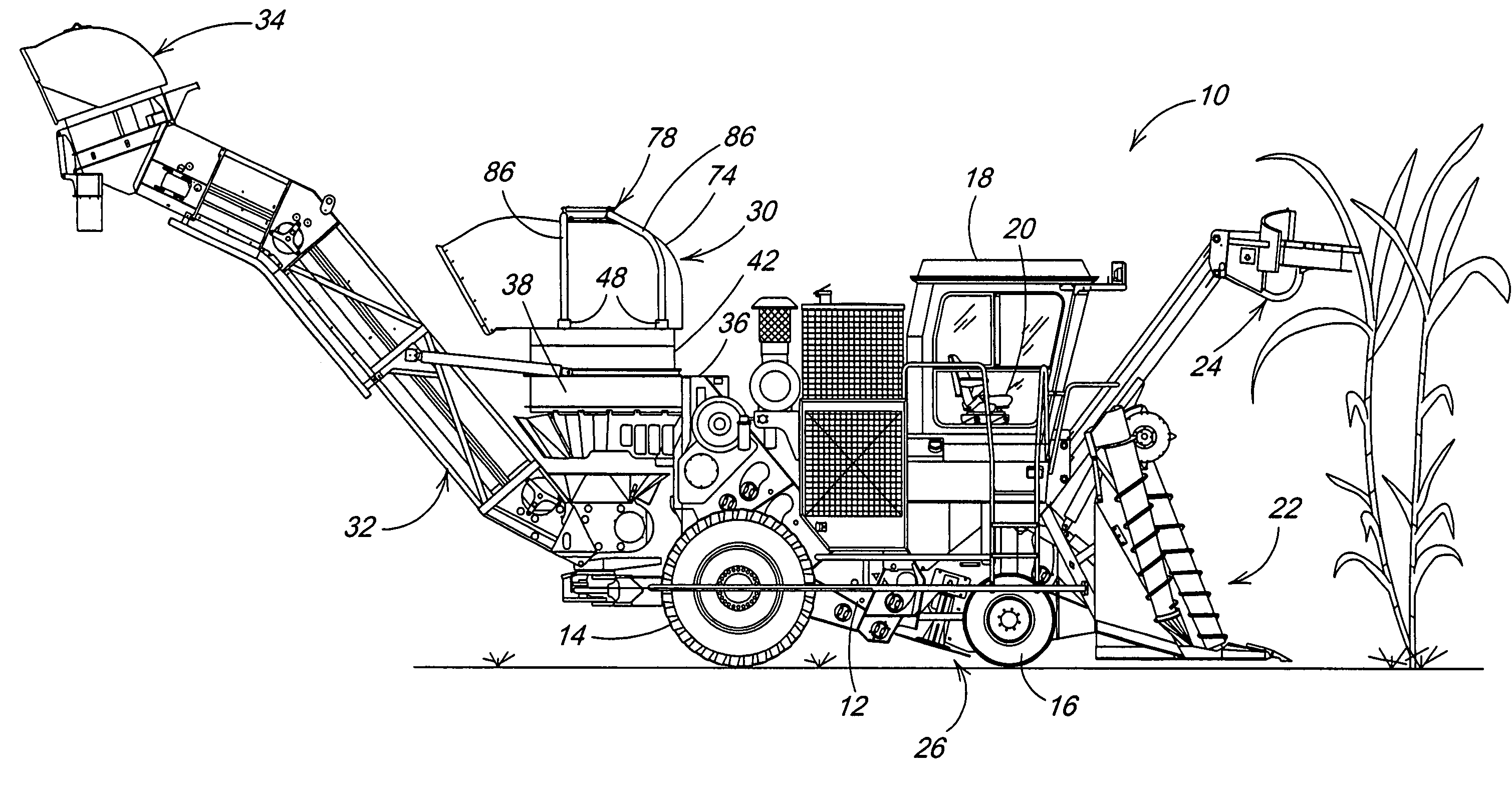
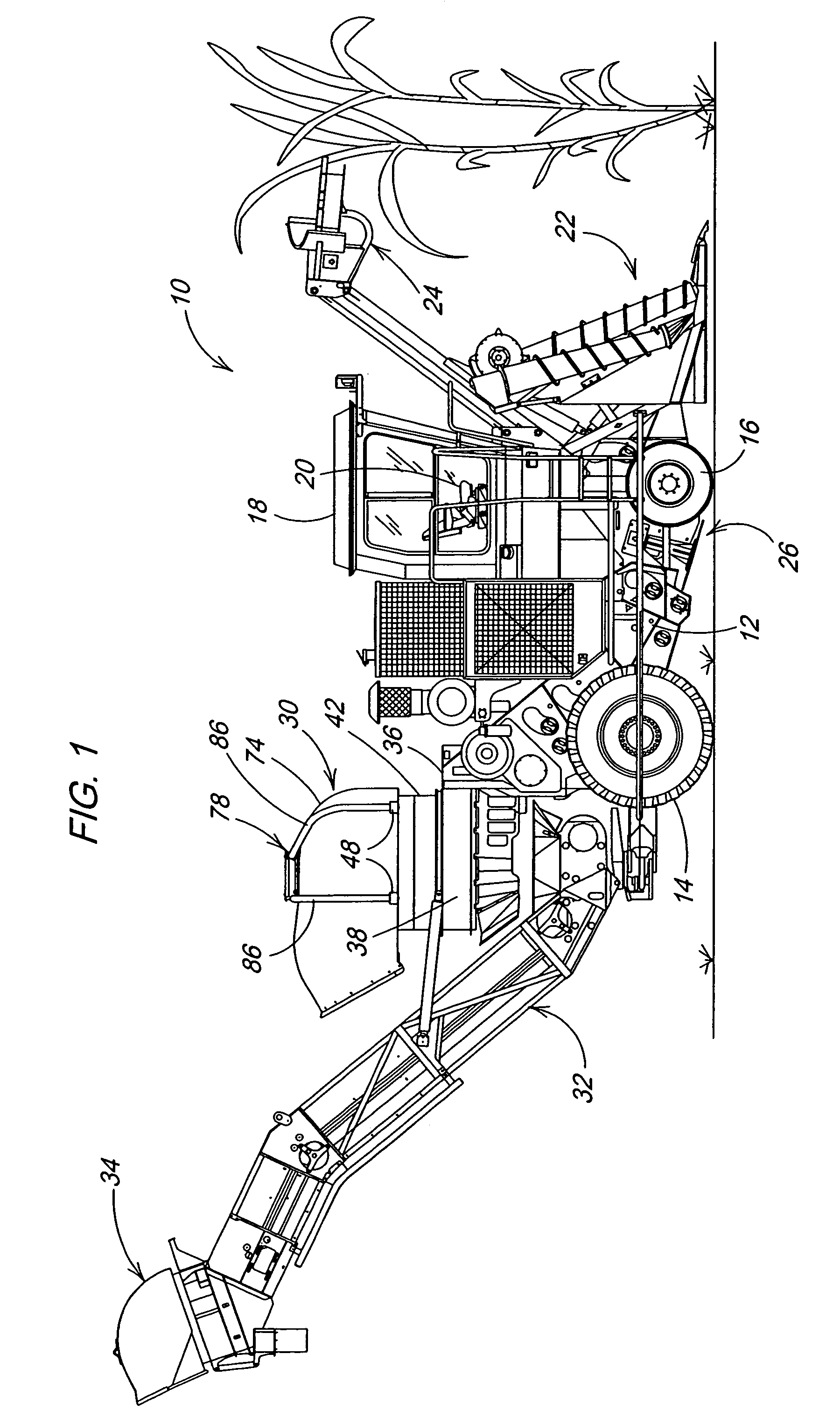
Referring now to FIG. 1, there is shown a sugarcane chopper harvester 10 including a main frame 12 supported on a pair of rear drive wheels 14 and a pair of steerable front wheels 16. An operator's cab 18 is mounted on a forward region of the frame 12 and contains a seat 20 from where an operator may view the operation of a pair of crop lifters 22, which would operate on opposite sides of a row of cane to be harvested, and the operation of a topper 24 mounted to the front of the frame 12. Located just to the rear of the front wheels 16 is a base cutter arrangement 26 including counter-rotating discs which cut off the stalks of cane close to the ground.

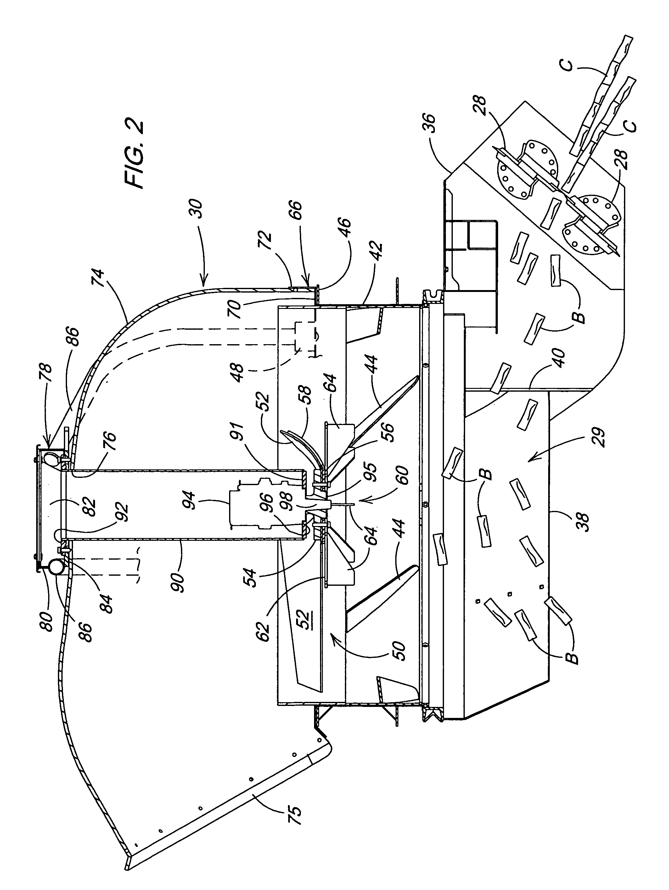
Referring now also to FIG. 2, it can be seen that, once severed, stalks of cane C are conveyed rearwardly and upwardly to a further conveying device in the form of a chopper mechanism including counter-rotating drum cutters 28 having overlapping blades which operate to cut the stalks of cane C into billets B and eject them into a cle...


PUM


Abstract

A sugarcane chopper harvester is equipped with a cleaning chamber for cleaning extraneous leafy matter and dirt from harvested and chopped cane delivered to the chamber. Located within the chamber is an axial flow fan for effecting an upward flow of air including a high-velocity, outer, ring-shaped upwardly flowing air stream. Mounted to the bottom of the axial flow fan is a blower wheel for creating an upwardly and outwardly flowing air stream beneath the center of the axial flow fan such that leafy matter and dirt passing into the middle of the cleaning chamber below the axial flow fan is caused to be directed outwardly to the high-velocity, ring-shaped stream of air.

Description

FIELD OF THE INVENTION The present invention relates to sugarcane harvesters, and more specifically relates to a cleaning chamber and method for cleaning extraneous leafy material and dirt from the chopped cane of a chopper harvester. BACKGROUND OF THE INVENTION Sugarcane chopper harvesters use airflow devices to generate a flow of air to separate the extraneous matter, such as leaves and dirt from the chopped sugarcane, and expel it from the flow of chopped cane. This separation occurs in what is known as a cleaning chamber. The most popular type of cleaning chamber has an axial flow fan, referred to as an extractor, as the air-generating device. The fan is mounted above the flow of chopped material and the unwanted material passes through the fan itself. The shape of the cleaning chamber is round to match the shape of the fan. The material to be separated is introduced into the cleaning chamber from one side and usually within two feet of the fan. At this distance from the fan, th...

Claims


Application Information

Patent Timeline
IPC IPC(8): A01D45/00A01D45/10
CPCA01D45/10
Inventor HINDS, MICHAEL LYNN
Owner DEERE & CO
Why Eureka
Try Eureka