Reciprocating saw blade extension with lateral offset

a reciprocating saw and blade technology, applied in the direction of metal sawing devices, metal sawing apparatus, manufacturing tools, etc., can solve the problems of blade bending, blade bending, and hard tooling when bending the blade to cu

Inactive Publication Date: 2005-03-29
REALE GEORGE S +1
View PDF10 Cites 37 Cited by
  • Summary
  • Abstract
  • Description
  • Claims
  • Application Information

AI Technical Summary

Benefits of technology

These and other objects are met by an extension that is attachable to the driving shaft of a reciprocating blade tool such as a saber saw. The extension is attached to the drive shaft and the blade is attached to the end of the extension. The extension places the blade at a position spaced laterally and longitudinally from the nominal point of attachment of the blade to the driving shaft, the lateral spacing placing the

Problems solved by technology

As a result, the housing of the tool can interfere with positioning of the blade in connection with some desirable cutting situations.
As a result of potential interference due to the width of the housing, the operator may attempt to incline the tool housing and lay the blade laterally against the surface while causing the blade to bend.
Bending the blade to cut also is hard on the tool, applying off center forces to the drive shaft, to the mounting of the blade to the drive shaft as well as the mounting of the drive shaft in the tool.
Attempting a flush cut by inclining the tool also often does not result in a clean flush cut.
The surface adjacent to the protrusion may be marred.
Mounting the blade on a cutting line that is laterally spaced from the reciprocating driving shaft has some of the same problems as attempting

Method used


Image

  • Reciprocating saw blade extension with lateral offset
  • Reciprocating saw blade extension with lateral offset
  • Reciprocating saw blade extension with lateral offset

Examples


Embodiment Construction

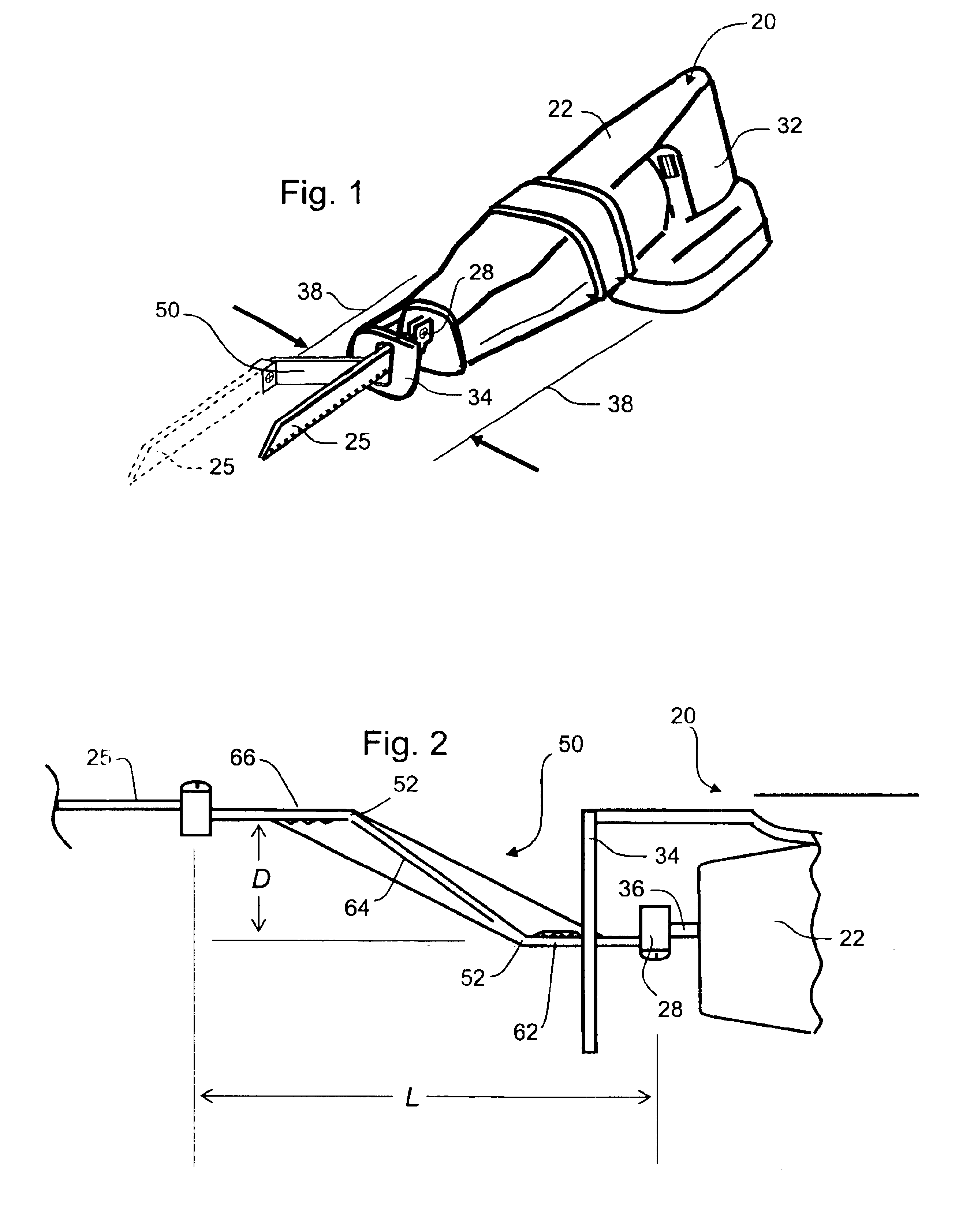
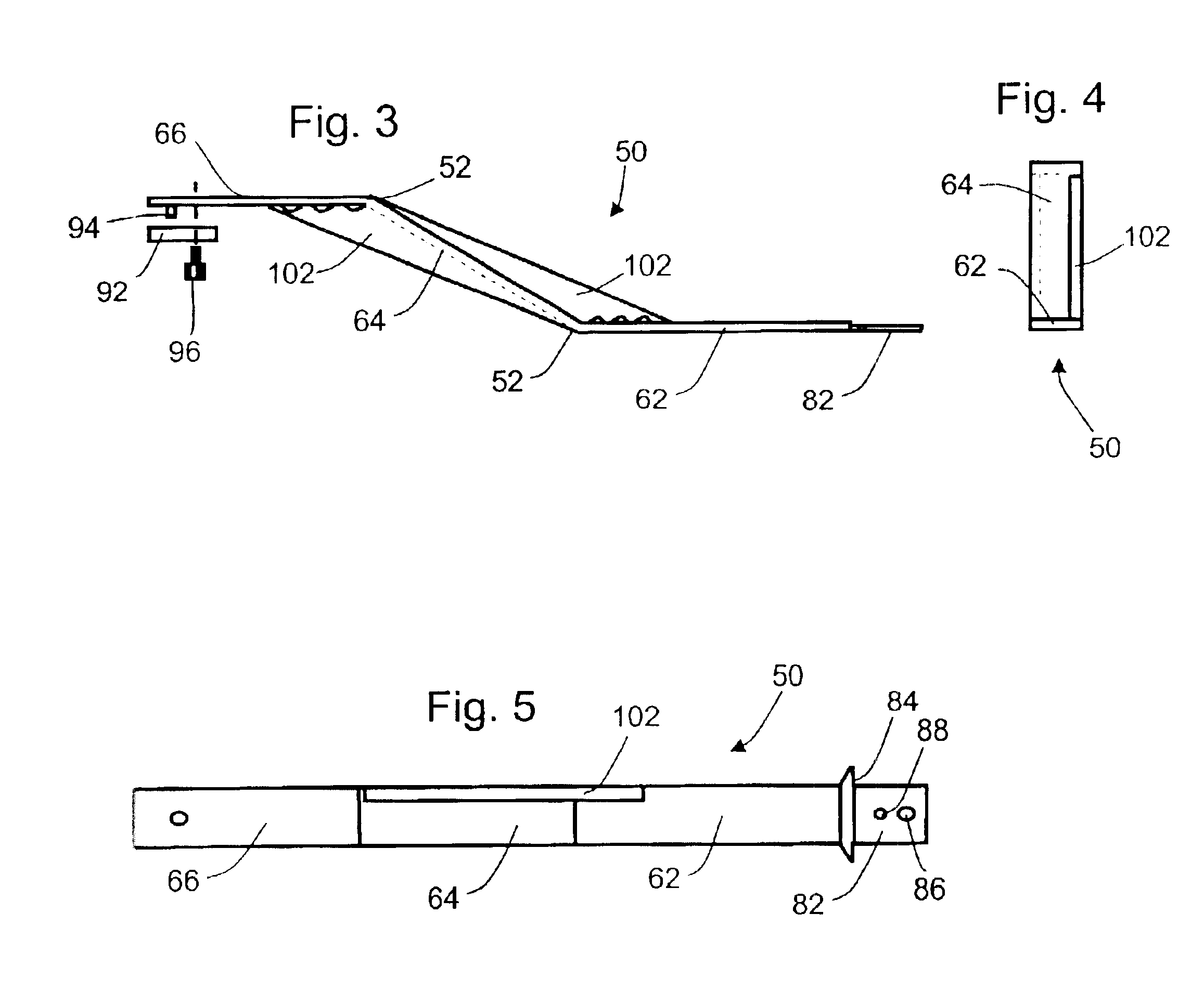
According to the invention an extension is attachable to the driving shaft of a reciprocating blade tool such as a saber saw. The extension is inserted between the normal connection for the blade, namely the reciprocating driving shaft, and the blade. That is, the extension is attached to the drive shaft and the blade is attached to the end of the extension. This is accomplished using structures for the opposite ends of the extension that resemble the structures of the blade and its point of drive shaft attachment, and which form a rigid extension that positions the blade at a longitudinal and lateral distance from its nominal directly-attached position on the reciprocating driving shaft of the tool.

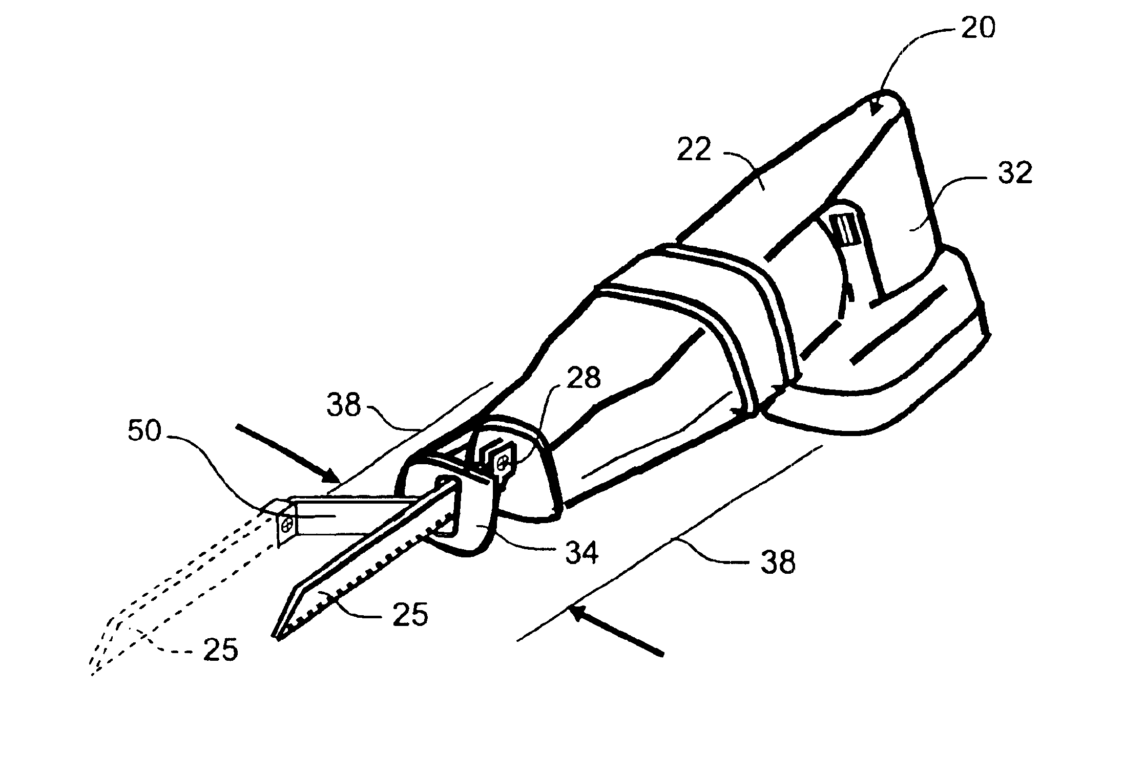
FIG. 1 illustrates an exemplary form of reciprocating blade tool 20. The tool has a housing 22 that carries an electric motor, pneumatic piston / cylinder or other mechanical arrangement (not shown) that reciprocates a serrated blade 25, attached to a fitting 28 at the end of a reciprocati...


PUM

PropertyMeasurementUnit
Angleaaaaaaaaaa
Distanceaaaaaaaaaa

Abstract

An extension is attachable to the driving shaft of a reciprocating blade tool such as a saber saw. The extension is attached to the drive shaft and the blade is attached to the end of the extension. The extension places the blade at a position spaced laterally and longitudinally from the nominal point of attachment of the blade to the driving shaft, the lateral spacing placing the new blade position approximately at the lateral outside edge of the tool housing, thereby permitting flush cuts. The extension can be formed of an integral strip or sheet having a proximal leg, an intermediate section and a distal leg, joined at equal and opposite obtuse angles. The angles are reinforced by two or more webs bent from the plane of the legs and attached, for example by welding, to the intermediate section.

Description

BACKGROUND OF THE INVENTION1. Field of the InventionThe invention concerns a blade mounting extension for a reciprocating saw such as a portable handheld electric saw. The blade mounting attaches at one end to a conventional flat saw blade and attaches at an opposite end to the conventional blade mounting fixture that otherwise would receive the saw blade. The inventive extension places the centerline of the saw blade at a lateral offset from the centerline of the blade mounting fixture, as well as spacing the blade linearly from the mounting fixture.2. Prior ArtA range of portable power tools provide for reciprocating motion and typically are powered electrically or pneumatically. The driving portion of such a power tool has a housing that requires a considerable lateral width and height, as well as depth in the direction of reciprocation, to support, guide and drive the shaft that carries the reciprocating element. An electric reciprocating tool, for example, typically has a rotat...

Claims


Application Information

Patent Timeline
IPC IPC(8): B23D49/00B23D51/10B23D51/00B23D49/11B23D49/16B23D61/12B27B11/00B27B19/00
CPCB23D51/10B23D49/11
Inventor REALE, GEORGE S.WOLF, PAUL F.
Owner REALE GEORGE S
Why Eureka
Try Eureka