Drive/auger anchor and stabilizer

Inactive Publication Date: 2005-03-29
MINUTE MAN ANCHORS
View PDF17 Cites 55 Cited by
  • Summary
  • Abstract
  • Description
  • Claims
  • Application Information

AI Technical Summary

Benefits of technology

A swivel connection connects the pressure cap with the drive section. The swivel connection allows the rod to be embedded in the ground soil at a first angle which is less than vertical while the downward surface of the cap is positioned flush against the surface of

Problems solved by technology

Due to disastrous effect of windstorms, tornadoes and hurricanes on manufactured homes, the housing industry now requires that all such homes be anchored in position.
It is sometimes difficult to meet these standards particularly in roc

Method used


Image

  • Drive/auger anchor and stabilizer
  • Drive/auger anchor and stabilizer
  • Drive/auger anchor and stabilizer

Examples


Embodiment Construction

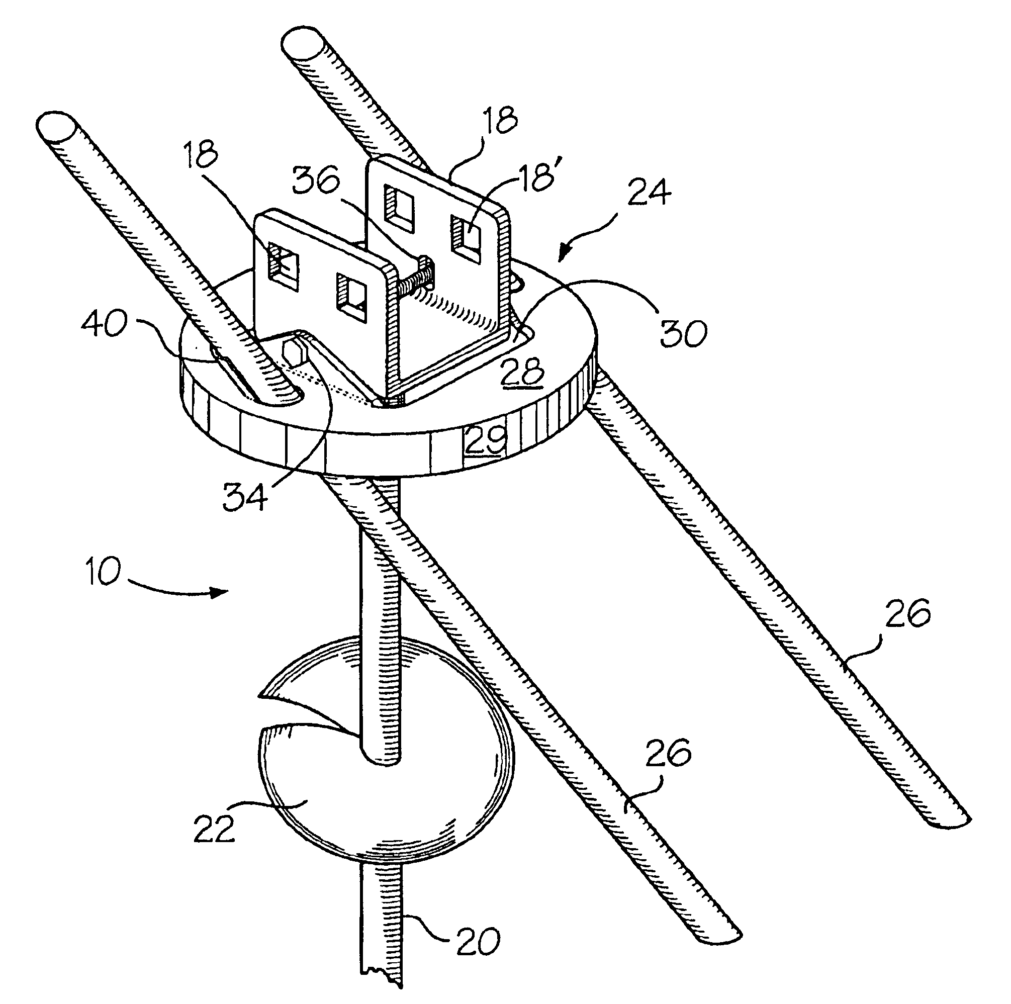
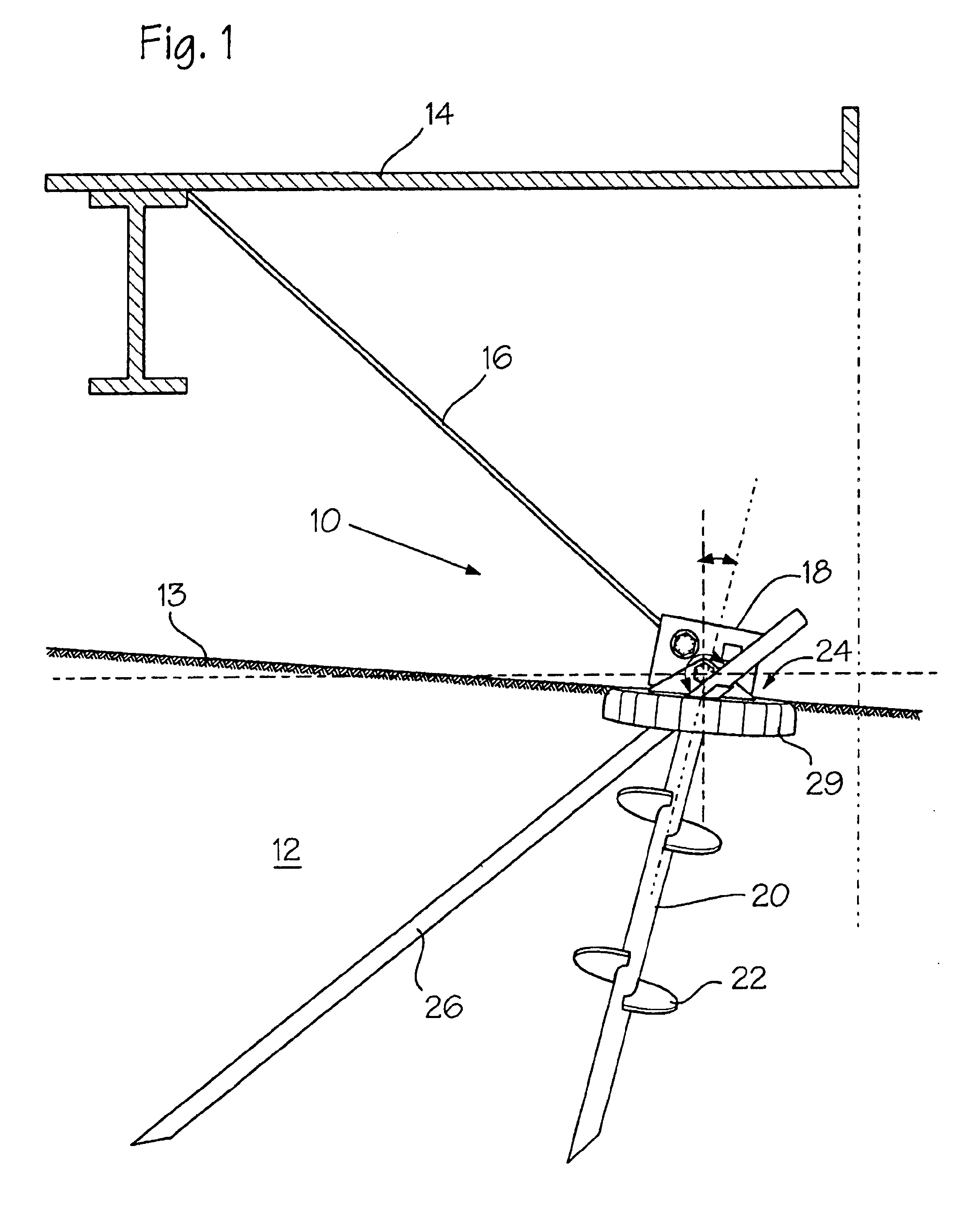
FIG. 1 shows anchor 10 secured in ground soil 12 and connected with a structure 14, usually a pre-constructed building, by cable 16. Anchor 10 includes a drive section or drive head 18, rod 20, augers 22, pressure cap 24 and spikes 26.

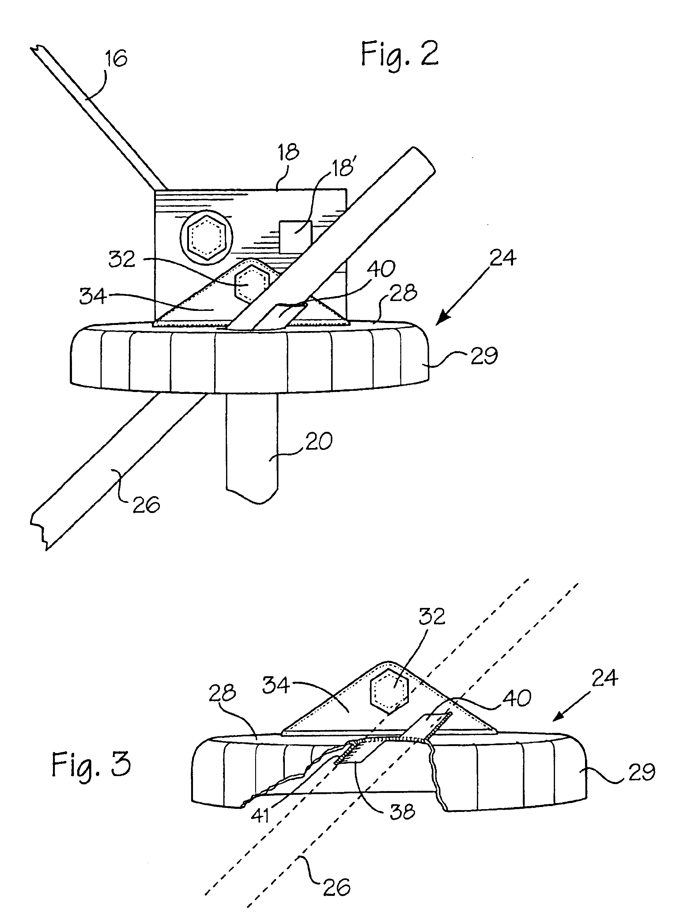
Turning now also to FIGS. 2 and 3, it can be seen that pressure cap 24 includes a planar area 28 having a down turned rim 29 and a central opening 30. A pair of up turned ears 34 are located in opposed positions adjacent opening 30. Bolt 32 passes through an opening 19 in each ear and also a pair of vertically elongated slots 36 in drive section 18. The connection between the drive head and the pressure cap allow both oscillating and vertical movement for cap 24. The result of this combination of movements creates a swiveling action. This arrangement is more fully discussed in U.S. Pat. No. 6,272,798 to Cockman. The patent also discloses the increased resistance to pressure that a properly seated pressure cap provides.

Referring now to the drawings, the...


PUM


Abstract

A reinforced ground anchor including a spike, a pressure cap having a planar surface, a rod having a drive section at one end, and a swivel connection connecting said pressure cap with the rod. An opening is formed in the pressure cap. A guide is located adjacent the opening. The pressure cap engages flush with the surface of the ground, due to the action of the swivel connection, when the rod is positioned in the ground soil and the spike passes through the opening to engage in the ground soil at an acute angle. The spike and the cap in combination with the rod provide the anchor with additional resistance against horizontal and vertical pressure.

Description

BACKGROUND OF THE INVENTIONThis instant invention is directed to a reinforced anchor primarily for use with manufactured homes.There is an ever-increasing effort in the manufactured housing industry to develop anchors capable of retaining position in the force of increased pressure, both horizontal and vertical. Due to disastrous effect of windstorms, tornadoes and hurricanes on manufactured homes, the housing industry now requires that all such homes be anchored in position. It is further required that such anchors withstand 4725 pounds of horizontal force with no more than 3″ of lateral movement of the head of the rod. Also, the anchor must withstand 4725 pounds of vertical pressure with no more than 2″ of head movement.It is sometimes difficult to meet these standards particularly in rocky soil where it is difficult to set the anchor at the normal 36″. Also, when the soil conditions are subject to drastic changes in consistency between being wet and dry or are excessively sandy t...

Claims


Application Information

Patent Timeline
IPC IPC(8): E02D5/80
CPCE02D5/801Y10T403/32975Y10S52/11Y10S256/05
Inventor COCKMAN, NORMAN FRANKWINN, SILAS E.
Owner MINUTE MAN ANCHORS
Why Eureka
Try Eureka