Heat sealing and cutting mechanism and container forming apparatus incorporating the same

a technology of sealing mechanism and cutting mechanism, which is applied in the field of packaging, can solve the problems of uneven distribution of hydraulic forces acting on the seal by the fluid in the tube above the seal, reduce the product life of milk, and reduce fill and seal machine, etc., and achieve the effect of effective sealing and increasing the cycle rate of the form

Inactive Publication Date: 2005-03-29
TOBOLKA STEFAN
View PDF13 Cites 21 Cited by
  • Summary
  • Abstract
  • Description
  • Claims
  • Application Information

AI Technical Summary

Benefits of technology

The present invention provides advantages in that the tube of packaging material can be sealed effectively even when the tube of packaging material is in the form of a laminate. This is due to the fact that since the heat sealing bands are configured to define temperature gradients along their lengths and across their widths, the temperature gradients reach the optimum sealing temperature of the laminate. Also, the present invention provides advantages in that the cutting wire ensures a clean cut through the tube between the closely spaced seals thereby avoiding the formation of “angel hair”. In addition since the heat sealing and cutting mechanisms are disposed on a set of jaws, the cycle rate of the form, fill and seal machine can be increased as compared to prior art machines.

Problems solved by technology

Unfortunately, gas and / or air in the packing container tends to decrease the product life of the milk introduced into the packing containers.
Although the above-described prior art methods allow seals to be formed across a fluid filled tube, these methods are only suitable when the seals to be formed across the tube are orthogonal to the longitudinal axis of the tube.
This is due to the fact that the hydraulic forces acting on the seal by the fluid in the tube above the seal are unevenly distributed along the seal.
If the tube is released after the seal is formed, the uneven hydraulic forces tend to move the tube off of its original plane making it difficult to regain control of the tube and subsequently form a cut across the tube along the seal.
Although the resistive wire method allows the tube to be sealed and cut simultaneously, it is also only suitable when orthogonal seals are to be formed across thin film packaging material.
This is due to the fact that it is difficult to maintain the shape of the resistive wire and control the pressure required for the resistive wire to seal and cut thicker or laminated packaging material.
Although these container forming apparatuses overcome problems associated with conventional container forming apparatuses by forming fluid filled containers devoid of air and / or other gasses, which extends product life, it has been difficult to control precisely the temperature of the heat sealing bars or heat sealing bands to suit the packaging material being sealed.
As a result, when dealing with laminated and / or co-extruded multi-layered packaging films, the heat sealing and cutting mechanisms have not yielded high integrity seals consistently over long run cycles.

Method used


Image

  • Heat sealing and cutting mechanism and container forming apparatus incorporating the same
  • Heat sealing and cutting mechanism and container forming apparatus incorporating the same
  • Heat sealing and cutting mechanism and container forming apparatus incorporating the same

Examples


Embodiment Construction

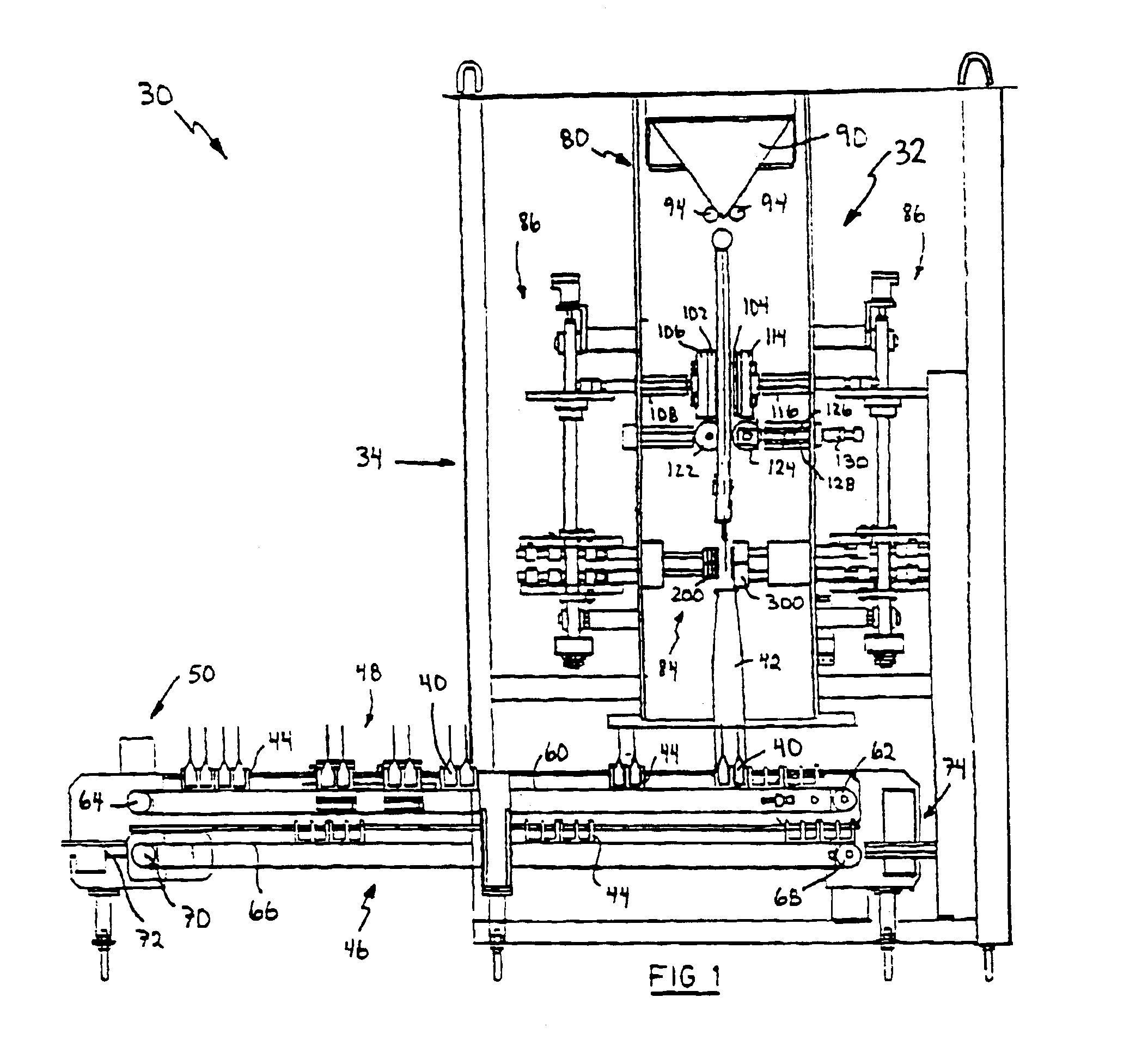
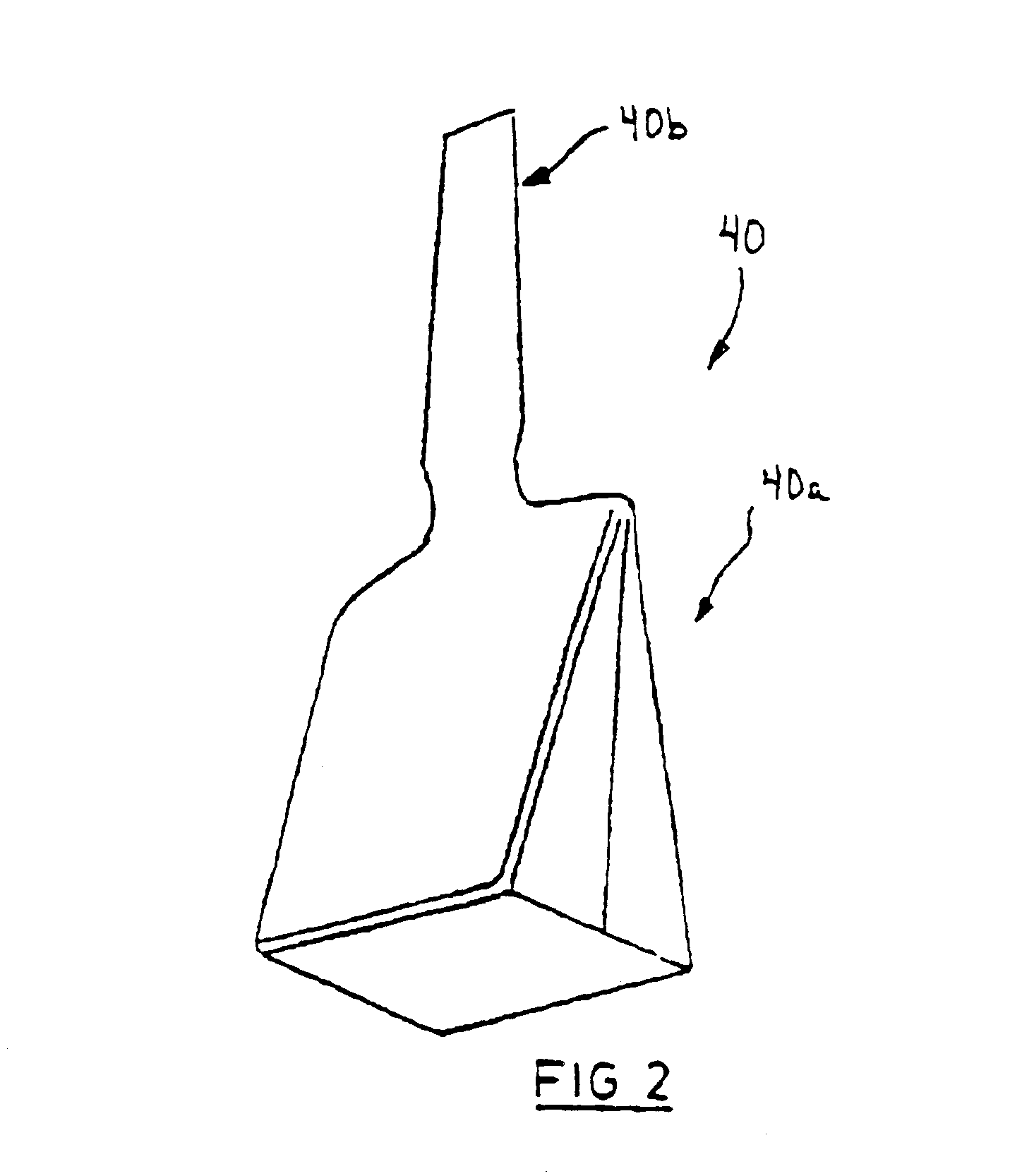
Referring now to FIGS. 1 and 2, a container forming and delivery system is shown and is generally indicated to by reference numeral 30. As can be seen, system 30 includes a container forming apparatus 32 mounted on a frame assembly 34 and receiving a web of flexible packaging material unwound from a roll (not shown). In the present embodiment, the packaging material is formed of laminated and / or co-extruded multi-layer plastic films. Currently, films of this nature seal within a temperature range from about 95° to 115° F. depending on the type of film. The roll of packaging material is supported on a motor driven shaft (not shown), which when rotated delivers packaging material to the container forming apparatus 32. Container forming apparatus 32 is of the form, fill and seal type and is operable to form individual fluid filled containers 40 (best seen in FIG. 2) from the web of packaging material. A diverter 42 is positioned below the container forming apparatus 32 and delivers the...


PUM

PropertyMeasurementUnit
temperatureaaaaaaaaaa
flexibleaaaaaaaaaa
heataaaaaaaaaa

Abstract

A heat sealing and cutting mechanism to form a heat seal and a cut across a tube of flexible packaging material includes a carrier to contact the tube. A pair of closely spaced heat sealing bands are disposed on the carrier and are energizable to form closely spaced heat seals across the tube when the carrier is in contact with the tube. The heat sealing bands are configured to define temperature gradients along the heat sealing bands. A cutting wire is also disposed on the carrier and is positioned between the heat sealing bands. The cutting wire is energizable to cut the tube when the carrier is in contact with the tube.

Description

FIELD OF THE INVENTIONThe present invention relates to packaging and in particular to a heat sealing and cutting mechanism and a container forming apparatus incorporating the same. The present invention also relates to a heat sealing blade.BACKGROUND OF THE INVENTIONForm, fill and seal packaging machines to form fluid filled containers from a tube of flexible packaging material are known in the art. For example, U.S. Pat. No. 4,747,253 to Schulte discloses an apparatus for the proportion of fluid contents during the manufacture of packing containers. The apparatus includes a filling tube extending into a tube of laminated packaging material to deliver milk into the tube of packaging material. A sealing mechanism below the filling tube forms transverse seals across the tube of packaging material to divide the tube of packaging material into individual cushion-shaped packing containers. Cuts are then formed along the seals to separate the individual packing containers. A gas feed pipe...

Claims


Application Information

Patent Timeline
Patent Type & Authority Patents(United States)
IPC IPC(8): B29C65/00B29C65/22B29C65/18B29C65/74B65B51/26B65B51/30
CPCB29C65/224B29C66/81871B29C65/745B29C65/7461B29C66/1122B29C66/244B29C66/3472B29C66/4312B29C66/7373B29C66/80B29C66/81457B29C66/8491B65B9/213B65B51/303B29C65/222B29C65/228B29C66/81811B29C66/81422B29C66/81427B29C66/81431B29C66/8167B65B9/2056B29C66/81423B29C65/743B29C66/83543B29C66/4322B29C66/43129B29C66/8226B29C66/723
Inventor TOBOLKA, STEFAN
Owner TOBOLKA STEFAN
Why Eureka
Try Eureka