
Display controller architecture for portable computers

a display controller and portable computer technology, applied in the field of portable computers, can solve the problems of inability to receive video signals, many portable computers b>10/b> becoming obsolete, and many portable computers b>10/b> can only output video signals

Inactive Publication Date: 2005-03-29
LENOVO PC INT
View PDF20 Cites 13 Cited by
  • Summary
  • Abstract
  • Description
  • Claims
  • Application Information

AI Technical Summary

Benefits of technology

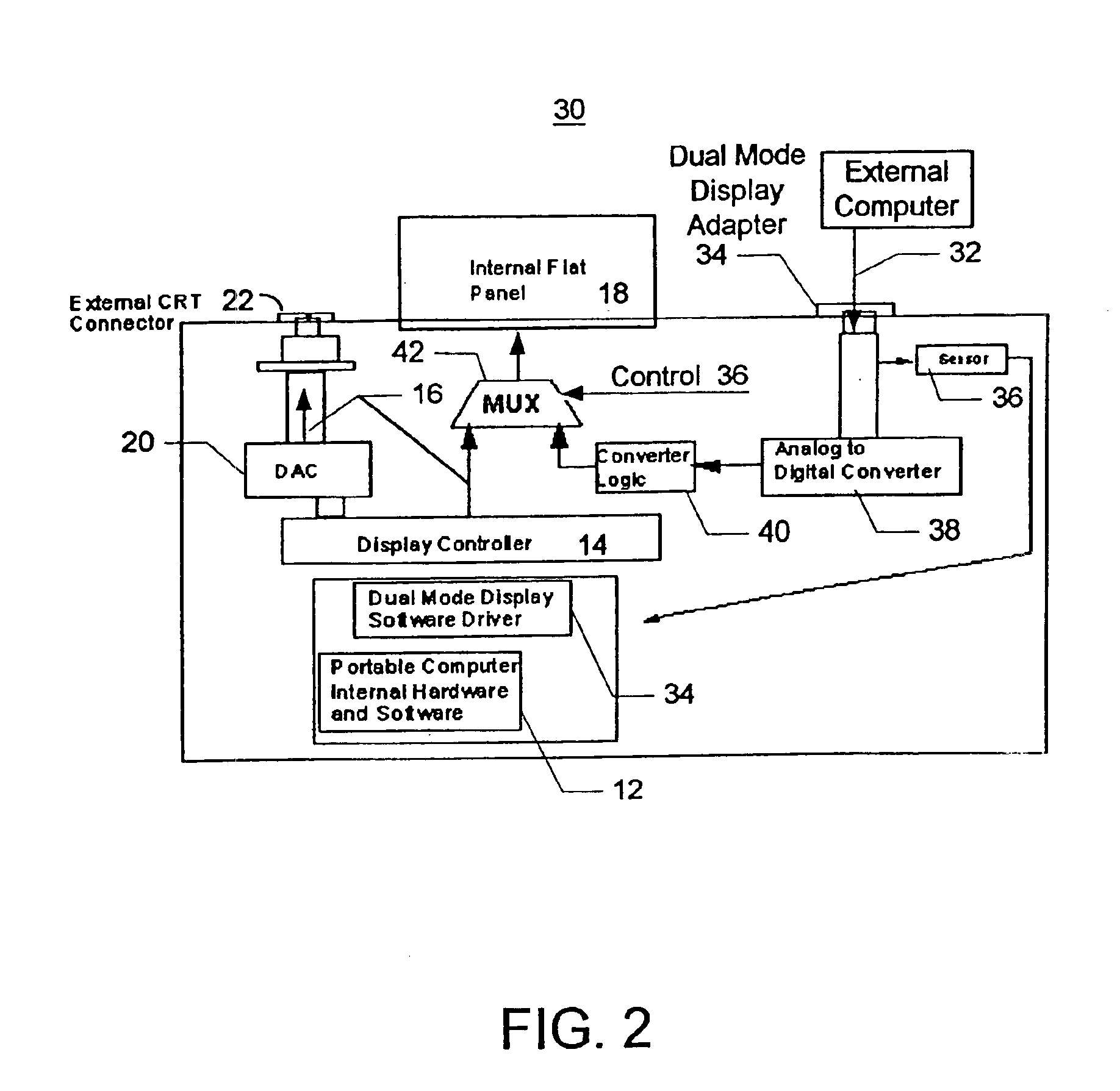
The present invention provides a dual display mode portable computer. The portable computer includes a flat-panel display, and a display controller for outputting an internal video signal to the flat panel display. The portable computer further includes means for receiving an external video signal, and a multiplexer for outputting the internal video signal to the flat-panel display during a first display mode, and for outputting the external video signal to the flat-panel display during a second display mode, thereby enabling the portable computer to act as a display device for an external computer.

Problems solved by technology

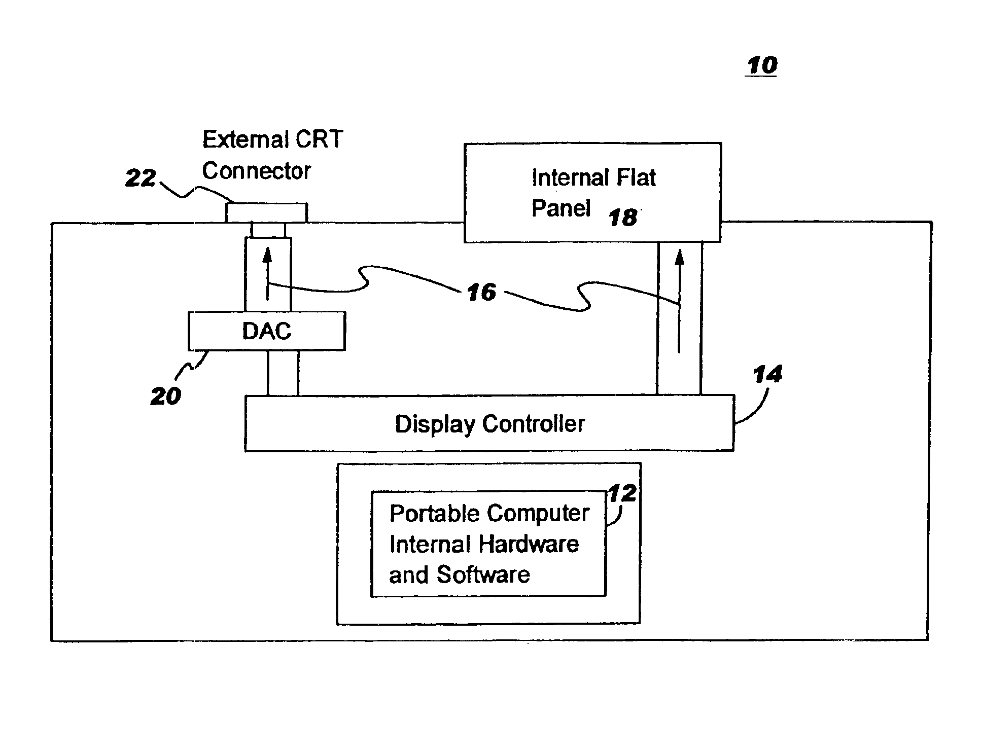
Yet, today many portables 10 become obsolete because various components, such as the processor, deliver lackluster performance relative to new computer systems.
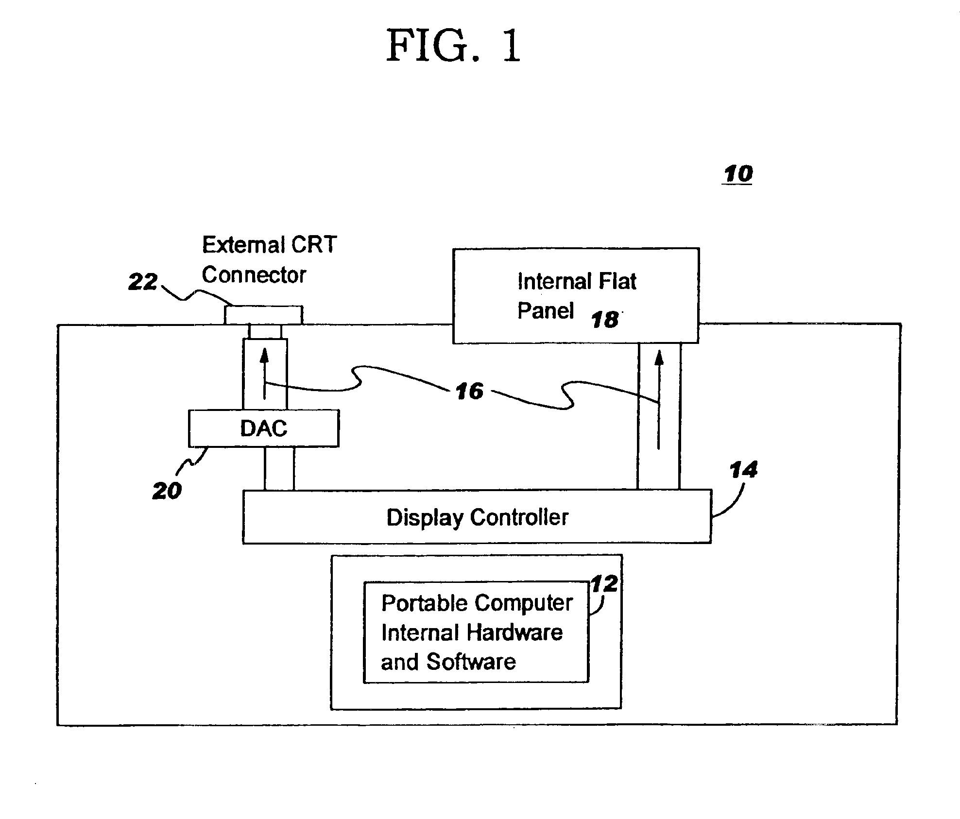
The problem is that today's portable computers 10 can only output video signals, but cannot receive video signals from an external source for display on the flat-panel 18.

Method used


Image

  • Display controller architecture for portable computers
  • Display controller architecture for portable computers
  • Display controller architecture for portable computers

Examples


first embodiment

In the present invention, the display controller architecture includes a dual mode display connector 34, a sensor 36, an analog-to-digital (A / D) converter 38, converter logic 40, and a multiplexer 42. In a preferred embodiment, the dual mode display connector 34 is a 15-pin RGB connector for coupling a video cable from an external PC or portable to the portable computer 30. The external video signal 32 preferably comprises RGB analog input and timing signals.

When the external video signal 32 is received on the connector 34, the A / D converter 38 converts the signal 32 into a digital signal. The converter logic 40 then maps the output of the A / D converter 38 into a format required by the flat panel display 18. After the conversion, the formatted digital video signal is input into the multiplexer 42. The multiplexer 42 has two inputs: the standard internal video signal 16 from the display controller 14, and the external video signal 32 output from converter logic 40. The multiplexer 42...

second embodiment

Referring now to FIG. 3, a display controller architecture is shown according to a second preferred embodiment of the present invention, where like components from FIGS. 1 and 2 have like reference numerals. The second embodiment adds a dual mode display connector 52 to the existing external CRT connector 22 of the portable computer 50 that connects to the external CRT connector 22, rather than adding a new connector to the portable computer. The CRT connector 22 is a female type connector. Therefore, the dual mode display connector 52 is a female to male type connector for accepting a display cord from another computer. The advantage of using the dual mode display connector 52 is that current portable computers do not have to be redesigned to accept a new input connector.

According to the second embodiment, a second multiplexer 54 is connected between the external CRT connector 22 and the D / A converter 20. In normal display mode, the D / A converter 20 outputs the internal video signa...


PUM


Abstract

A dual display mode portable computer is disclosed. The portable computer includes a flat-panel display, and a display controller for outputting an internal video signal to the flat panel display. The portable computer further includes means for receiving an external video signal, and a multiplexer for outputting the internal video signal to the flat-panel display during a first display mode, and for outputting the external video signal to the flat-panel display during a second display mode, thereby enabling the portable computer to act as a display device for an external computer.

Description

FIELD OF THE INVENTIONThe present invention relates to portable computers, and more particularly to a display controller architecture for portable computers.BACKGROUND OF THE INVENTIONLaptops and notebooks are names for portable computers that have a flat screen and usually weigh less than eight pounds. Most portable computers have connectors for an external monitor and keyboard for transforming them into desktop computers.FIG. 1 is a block diagram illustrating current display technology found in portable computers. Like most computer systems, a portable computer 10 includes internal hardware and software 12 for operating the system, and a display controller 14 for outputting an internal video signal 16 to a flat panel display 18. The portable computer 10 also includes a digital-to-analog converter 20 and an external CRT connector 22 for outputting the video signal 16 to an external monitor, such as a cathode ray tube (CRT) (not shown). With this type of display architecture, the po...

Claims


Application Information

Patent Timeline
IPC IPC(8): G06F1/16G06F3/14G09G3/20G09G5/00
CPCG06F1/1613G09G5/006G06F3/1407G06F1/1632G06F3/147G09G5/003G09G2370/20
Inventor HANSEN, JILL ANNRENGAN, MARCO MICHAELWOLFORD, ROBERT RUSSELLZABELICKY, JR., RICHARD JOSEPH
Owner LENOVO PC INT
Learn More