
Image encoding system, image decoding system and methods therefor

a technology of image data and decoding system, applied in the field of image data compression, can solve the problems of image data volume so large, deterioration of visual quality of decoded images, and volume of communication or storag

Inactive Publication Date: 2005-03-29
FUJIFILM BUSINESS INNOVATION CORP
View PDF7 Cites 4 Cited by
  • Summary
  • Abstract
  • Description
  • Claims
  • Application Information

AI Technical Summary

Benefits of technology

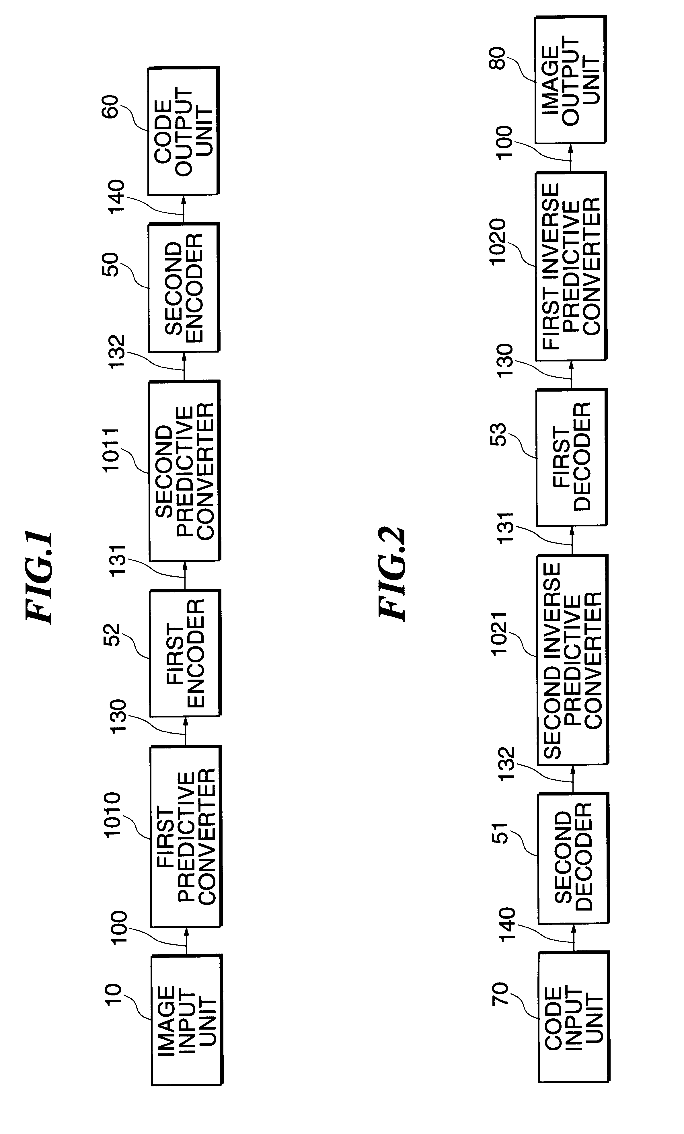
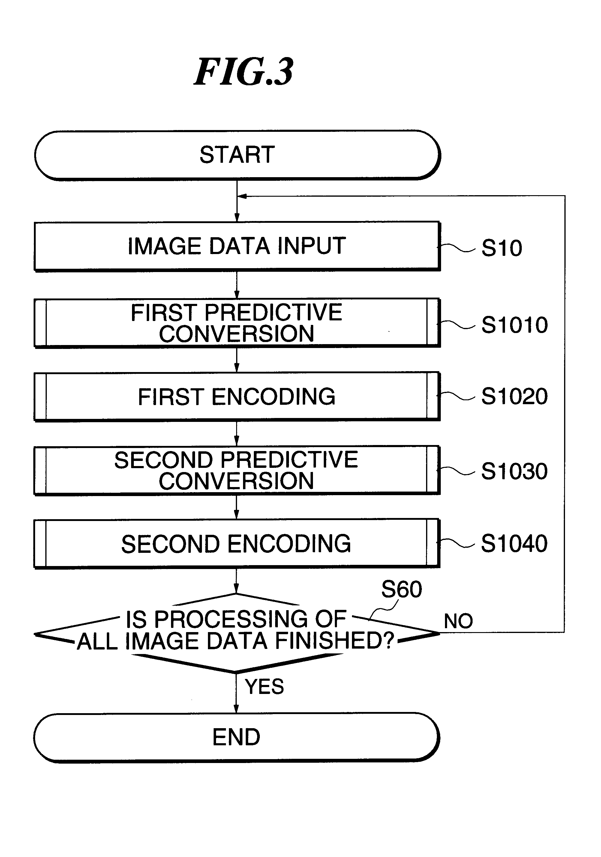
Thus, the present invention makes it possible to encode an image signal according to its locality by converting it into a first prediction value, and also to eliminate redundancy caused by periodicity of intermediate data by converting the intermediate data generated by encoding the first prediction into a second prediction value.
Thus, the present invention decodes an encoded signal to generate a second prediction value, and converts the second prediction value inversely. This generates intermediate data with periodicity. In addition, this intermediate data is decoded to generate a first prediction value, which is then converted inversely. This makes it possible to obtain an image signal which reproduces image locality.

Problems solved by technology

Generally volumes of image data are so huge that it is often compressed to reduce its volume for communications or storage.
In irreversible encoding methods, visual deterioration in the quality of decoded images may occur depending on the compression rate.
However, the related art has the following problems.
Images with periodicity as illustrated here are difficult to encode efficiently by a conventional method based on the related art.
On the other hand, data in the second and the third line have a cyclic pattern, but its compressibility is low in the conventional method.
1. Only a dither which corresponds to the predictor position can be used.
2. Since the number of predictors increases, the volume of prediction condition data 130 also increases and thus the compressibility decreases.
3. The increase in the number of predictors makes prediction processing more complicated and thus decreases the processing speed.
As discussed so far, the major problem of the related art is that it is impossible to compress an image with periodicity efficiently because pixels adjacent to the target pixel are mainly used for prediction processing.
Furthermore, in order to prevent this, many predictors must be added, which also contributes to the problem of efficiency reduction.

Method used


Image

  • Image encoding system, image decoding system and methods therefor
  • Image encoding system, image decoding system and methods therefor
  • Image encoding system, image decoding system and methods therefor

Examples


first embodiment

the present invention is explained next. FIGS. 1 and 2 are block diagrams representing an image encoding system and an image decoding system in the first embodiment, respectively. In these figures, the same reference numerals as used in FIGS. 14 and 15 designate the same elements, so only elements other than those elements are described here. 52 denotes a first encoder, 53 a first decoder, 131 prediction symbol data, 132 higher-level symbol data, 1011 a second predictive converter and 1021 a second inverse predictive converter.

As shown in FIG. 1, the first predictive converter 1010 receives image data 100 from the image input unit 10 to convert it in a given manner for prediction and sends the resulting data as prediction condition data (first prediction value) 130 to the first encoder 52.

The first encoder 52 encodes the prediction condition data 130 using a prescribed encoding technique and sends the encoded data as prediction symbol data (intermediate data) 131 to the second predi...

second embodiment

Described next is the present invention. FIGS. 7 and 8 show an image encoding system block diagram and an image decoding system block diagram, respectively. In these figures, the same elements as used in FIGS. 1, 2, 14 and 15 are marked with the same reference numerals and their descriptions are omitted here. 22 represents a third predictor, 23 a fourth predictor, 42 and 43 second selectors, 112 prediction data, and 113 control data.

The elements shown in FIG. 7 are described next. The third predictor 22 and the fourth predictor 23 each make a prediction for the prediction target symbol according to prediction symbol data 131 in a given manner and send the resulting data as prediction data 112 to the second selector 42. The second selector 42 detects whether the prediction for the prediction target symbol is right or wrong, according to the prediction symbol data 131 and the prediction data 112. As a result, if the prediction made by either predictor is right, the predictor's ID numb...


PUM


Abstract

A system and method are provided for realizing high speed and high efficiency in compression of image data having periodicity. The present invention includes the following: an image input unit to input image signal; a first predictive converter which converts relation between the pixel value of a target pixel in the image signal inputted through the image input part and that of another pixel into a first prediction value; a first encoder which generates intermediate data by encoding the first prediction value output from the first predictive converter; a second predictive converter which converts relation between a target symbol among symbols making up the intermediate data generated by the first encoder and another symbol into a second prediction value; and a second encoder which generates an encoded signal by encoding the second prediction value output from the second predictive converter.

Description

BACKGROUND OF THE INVENTION1. Field of the InventionThis invention relates to technology of image data compression, particularly to an image encoding system which performs compression encoding of multivalued input image data and an image decoding system which converts compressed encoded data back into its original form, and an image encoding method and an image decoding method.2. Description of Related ArtGenerally volumes of image data are so huge that it is often compressed to reduce its volume for communications or storage. Image encoding methods are broadly classified into two types: a reversible type and an irreversible type. In irreversible encoding methods, visual deterioration in the quality of decoded images may occur depending on the compression rate.On the other hand, if a reversible encoding method, in which encoded data is converted into its original form to produce the same image as an input image, is used, the problem of image quality deterioration can be prevented. A...

Claims


Application Information

Patent Timeline
Patent Type & Authority Patents(United States)
IPC IPC(8): G06T9/00H04N1/41H04N19/50H03M7/46H04N19/593H04N19/91H04N19/93
CPCH04N1/4105G06T9/004
Inventor YOKOSE, TARO
Owner FUJIFILM BUSINESS INNOVATION CORP
Learn More