
Method and system for tracking two communications participants of an optical satellite communications system

Inactive Publication Date: 2012-02-16
ASTRIUM GMBH
View PDF4 Cites 5 Cited by
  • Summary
  • Abstract
  • Description
  • Claims
  • Application Information

AI Technical Summary

Benefits of technology

[0009]Embodiments of the present invention relate to a method and a system with which an improved tracking performance of two communications participants of an optical satellite communications system is achieved.
[0013]In this manner a better accuracy compared to the prior art can be achieved in determining the phase angle and the tracking of the two communications participants based on the signal transmitted between them, which optionally is a beacon signal. The improved tracking accuracy can be used in order to use a greater focusing of the transmission beam and to achieve a higher range resulting therefrom or, with the same range, to achieve a saving in terms of the transmitting power required. If the power is used to increase the range, high data rate deep space connections can be realized under these conditions.
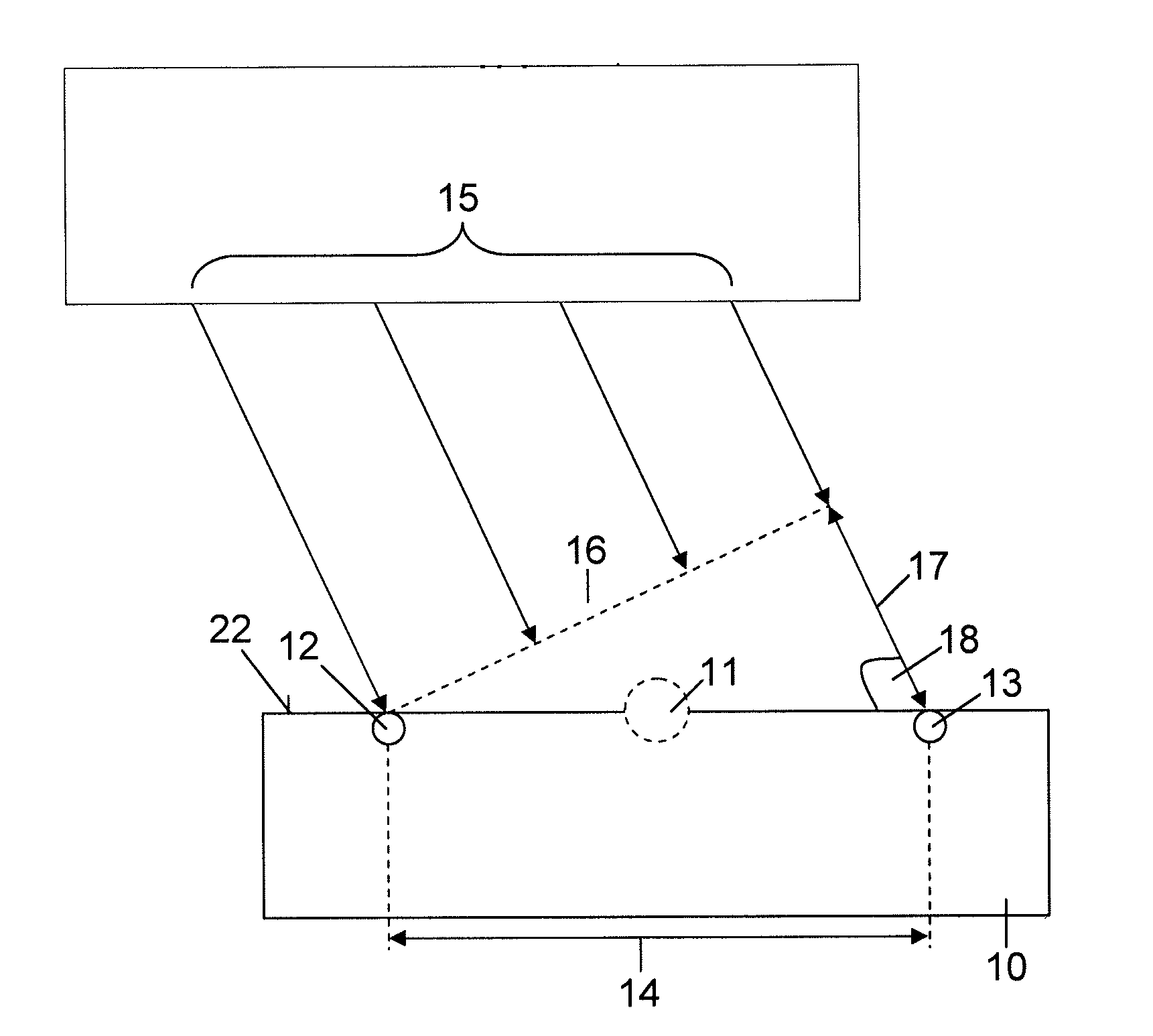
[0018]Based on the wavelengths used in the optical range and the phase inaccuracy resulting therefrom in the transit time difference or path difference which results in an ambiguity, a possibility for eliminating this ambiguity is used. According to an expedient embodiment of this type, the periodicity of the respective phase is eliminated using an FMCW frequency ramp. If the different detectors are tuned to only one step frequency, the different detectors receive the ramp shaped signal at this tuning frequency at different times. If the signal is to be received at only one point in time, the respective detectors then receive the signal at different frequencies. Ideally, with an optimum alignment of the respective terminals to one another, all of the detectors receive the received signal on the same frequency at the same time. The bandwidth of the frequency ramp signal is selected with reference to the Doppler effect to be expected. The detectors are tuned to the center of the step frequency or frequency ramp, so that the possible Doppler effect can be eliminated to the maximum extent with a positive as well as with a negative frequency shift.
[0022]The system according to the invention has the same advantages as are described above in connection with the method according to the invention. In particular, the system according to the invention renders possible an improved tracking accuracy. The range between the first and second communications participants can be increased due to the possible stronger beam focusing of the signal. In particular, the range can be more than 100,000 km. Alternatively, transmitting power required can be saved due to the improved tracking accuracy if an original distance between the two communications participants is retained. In the latter case, a higher data rate can also be achieved while retaining the transmitting power but at the same time reducing the beam focusing.
[0032]In accordance with further embodiments of the invention, using an FMCW (frequency step CW signal) frequency ramp, an ambiguity of the phase difference with respect to 2 Pi and a confinement of the possible measuring range to be corrected can be eliminated.

Problems solved by technology

One disadvantage of the tracking method based on the evaluation of amplitude maxima is the lack of accuracy.
This results among other things from the fact that the optical communication used as well as the OOK and PSK modulation methods thereof used are subject to atmospheric influences.

Method used


Image

  • Method and system for tracking two communications participants of an optical satellite communications system
  • Method and system for tracking two communications participants of an optical satellite communications system

Examples


Embodiment Construction

[0044]The particulars shown herein are by way of example and for purposes of illustrative discussion of the embodiments of the present invention only and are presented in the cause of providing what is believed to be the most useful and readily understood description of the principles and conceptual aspects of the present invention. In this regard, no attempt is made to show structural details of the present invention in more detail than is necessary for the fundamental understanding of the present invention, the description taken with the drawings making apparent to those skilled in the art how the several forms of the present invention may be embodied in practice.

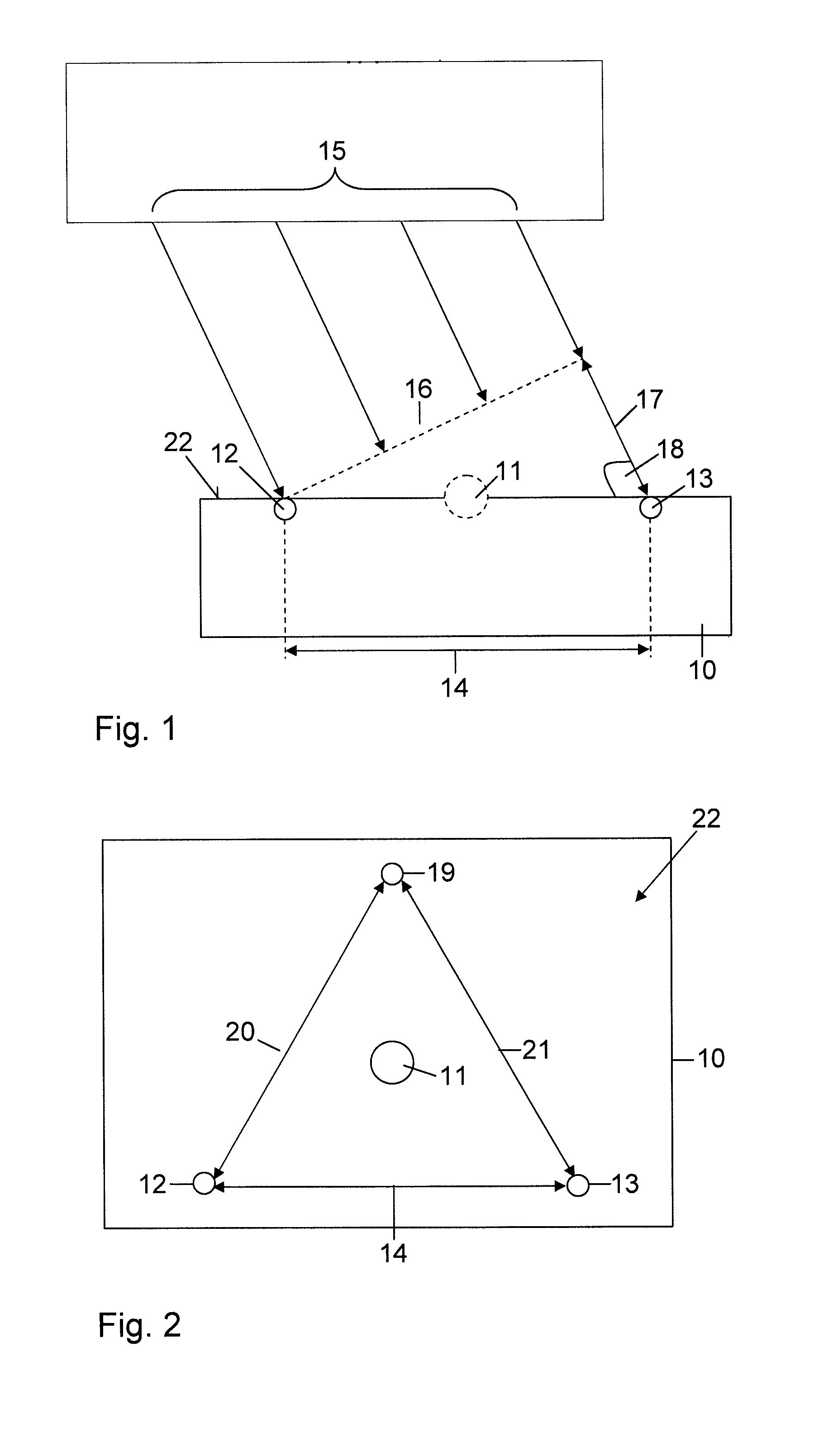
[0045]The method according to the invention for tracking two communications participants of a satellite communications system, which is also known as tracking, is based on the evaluation of respective phase differences of a signal received by several detectors of a detector arrangement of a communications participant. The...


PUM


Abstract

Method and system for tracking between two communications participants of an optical satellite communications system to provide a communication connection between the two communications participants. The method includes transmitting a signal from a first of the two communications participants to a second of the two communications participants, in which the second communications participant includes a detector arrangement with a plurality of detectors in a common receiving plane. The method also includes acquiring a phase of the signal at each of the plurality of detectors and determining phase differences between the phases via a phase-processor, determining from the phase differences a phase angle of an alignment of the signal to the receiving plane, processing the phase angle with a tracking computer in order to align the receiving plane of the second communications participant with the signal, whereby the phase difference becomes zero, and continuously calibrating the plurality of detectors of the detector arrangement.

Description

CROSS-REFERENCE TO RELATED APPLICATIONS[0001]The present application claims priority under 35 U.S.C. §119 of German Patent Application No. DE 10 2010 034 065.0, filed on Aug. 11, 2010, the disclosure of which is expressly incorporated by reference herein in its entirety.BACKGROUND OF THE INVENTION[0002]1. Field of the Invention[0003]The invention relates to a method and a system for tracking two communications participants of an optical satellite communications system, in particular of a satellite and a ground station, to provide an optical communication connection between the two communications participants.[0004]2. Discussion of Background Information[0005]With so-called intersatellite link (ISL) communication based on data transmission technologies in the optical range between LEO (Low Earth Orbit) satellites and ground stations or GEO satellites and ground stations, on-off keying (OOK) is typically used as a modulation method. The referenced ISL communication is usually based on...

Claims


Application Information

Patent Timeline
IPC IPC(8): H04B10/08H04B10/118
CPCG01S3/023G01S3/42G01S3/46H04B10/118
Inventor VON SCHWAKE, JENS
Owner ASTRIUM GMBH
Learn More