Hydrotherapy jet

a technology of hydrotherapy and jets, applied in the field of hydrotherapy jets, can solve the problems of increasing the number of system components, increasing the cost and weight of such systems, and increasing the complexity of such systems, so as to reduce the frequency of oscillation of flappers and reduce the periodicity of rotational movements

Inactive Publication Date: 2012-01-10
B & S PLASTICS
View PDF6 Cites 4 Cited by
  • Summary
  • Abstract
  • Description
  • Claims
  • Application Information

AI Technical Summary

Benefits of technology

[0007]A hydrotherapy jet apparatus is disclosed that includes a jet body having open upstream and downstream ends and defining a flow path between them, a flapper disposed within the flow path, the flapper having upstream and downstream flapper ends with the flapper rotatably connected to the jet body at the upstream flapper end to rotatably oscillate about the upstream flapper end when a stream of water is introduced from upstream to downstream through the flow path. A head spoiler is formed on the downstream flapper end to reduce the frequency of oscillation of the flapper, so that a stream of water pulsating effect is felt by a user of the jet apparatus adjacent the open downstream end as the flapper rotatably oscillates.
[0009]A method is disclosed that provides fluid flow through an internal flow path of a jet body, induces periodic rotational movement of a flapper disposed within the internal flow path about an upstream edge of the flapper in response to the fluid flow, and deflects fluid flow with a flapper head on the flapper to reduce the periodicity of the periodic rotational movement of the flapper.
[0010]A spa system is disclosed that includes a tub shell capable of holding a human being partially submerged below water when water is present in the tub shell, the tub shell having a drain and a spa jet body opening and a jet body coupled to the spa jet body opening. The jet body includes an open upstream end and an open downstream end and defining a flow path between the open upstream end and the open downstream end, a flapper disposed within the flow path, the flapper having a upstream flapper end and downstream flapper end, the flapper rotatably connected to the jet body at the upstream flapper end to rotatably oscillate about the upstream flapper end when a stream of water is introduced from upstream to downstream through the flow path, and a head spoiler formed on the downstream flapper end to reduce the frequency of oscillation of the flapper. The spa system also includes a water pump and a plurality of water conduits to connect the water pump to the drain and to connect the water pump to the jet body.

Problems solved by technology

Unfortunately, use of either rotating mechanical or hydraulic pumping devices increases system component count and adds complexity in comparison to fixed jet systems, thus increasing the cost and weight of such systems.

Method used


Image

  • Hydrotherapy jet
  • Hydrotherapy jet
  • Hydrotherapy jet

Examples


Embodiment Construction

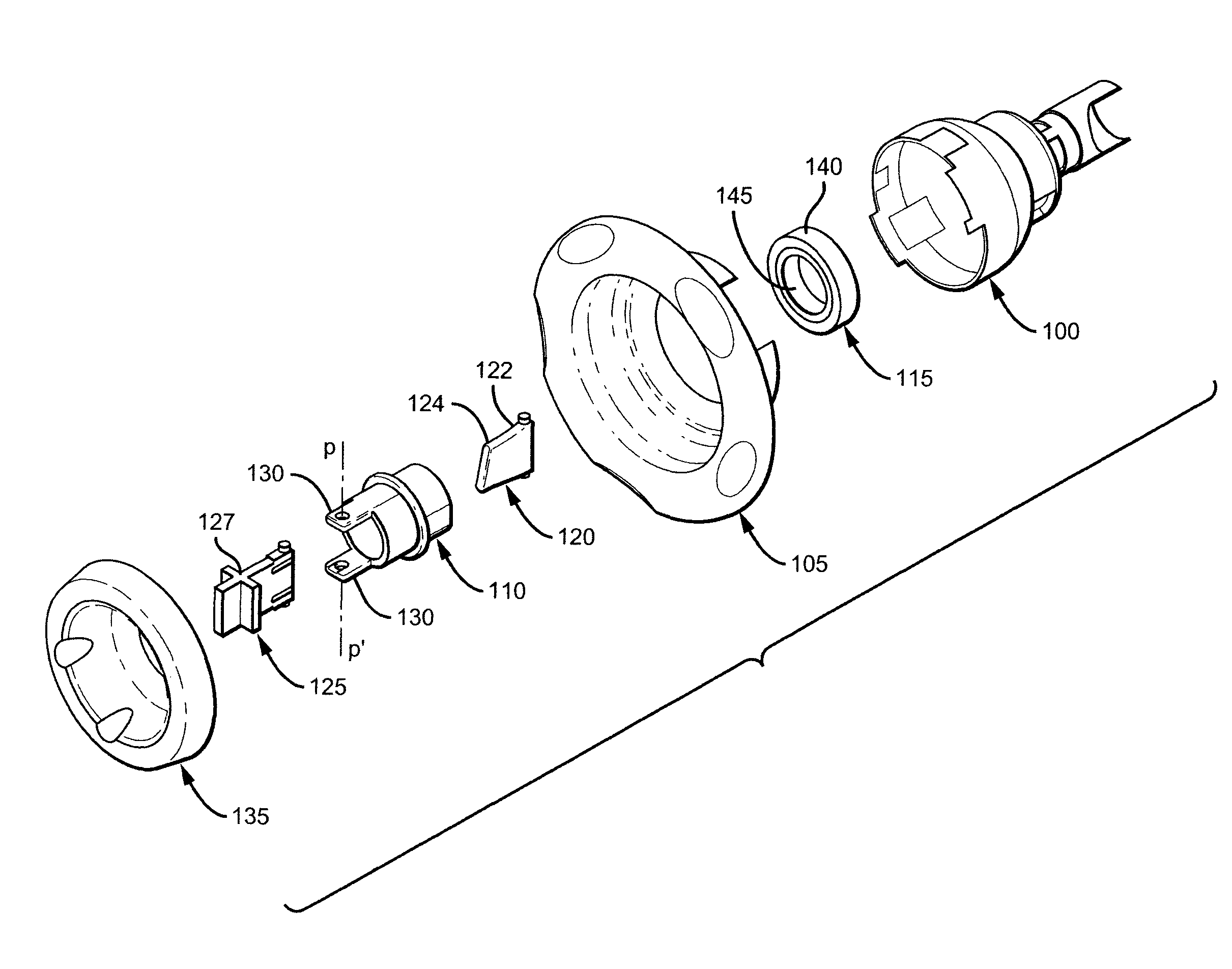
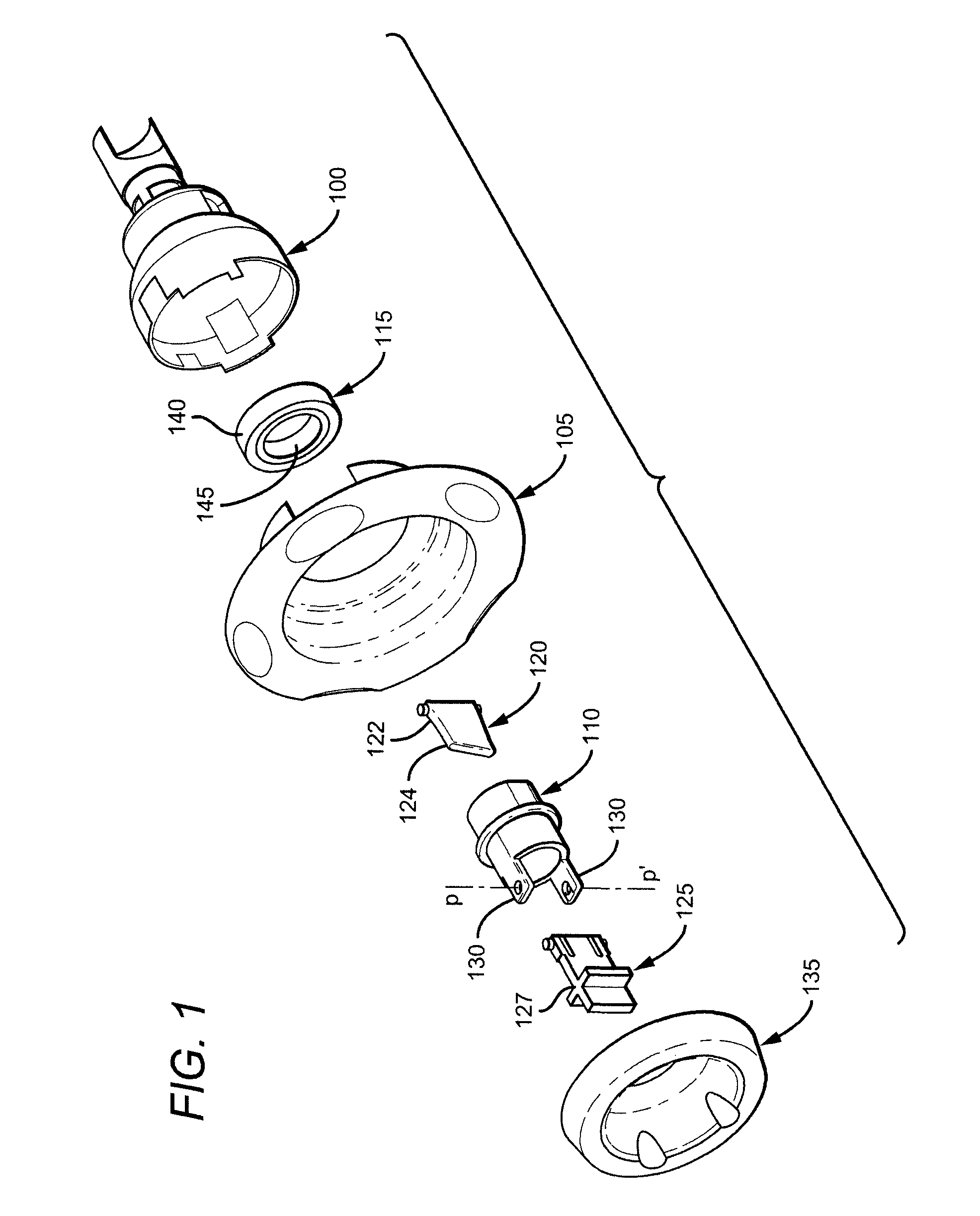
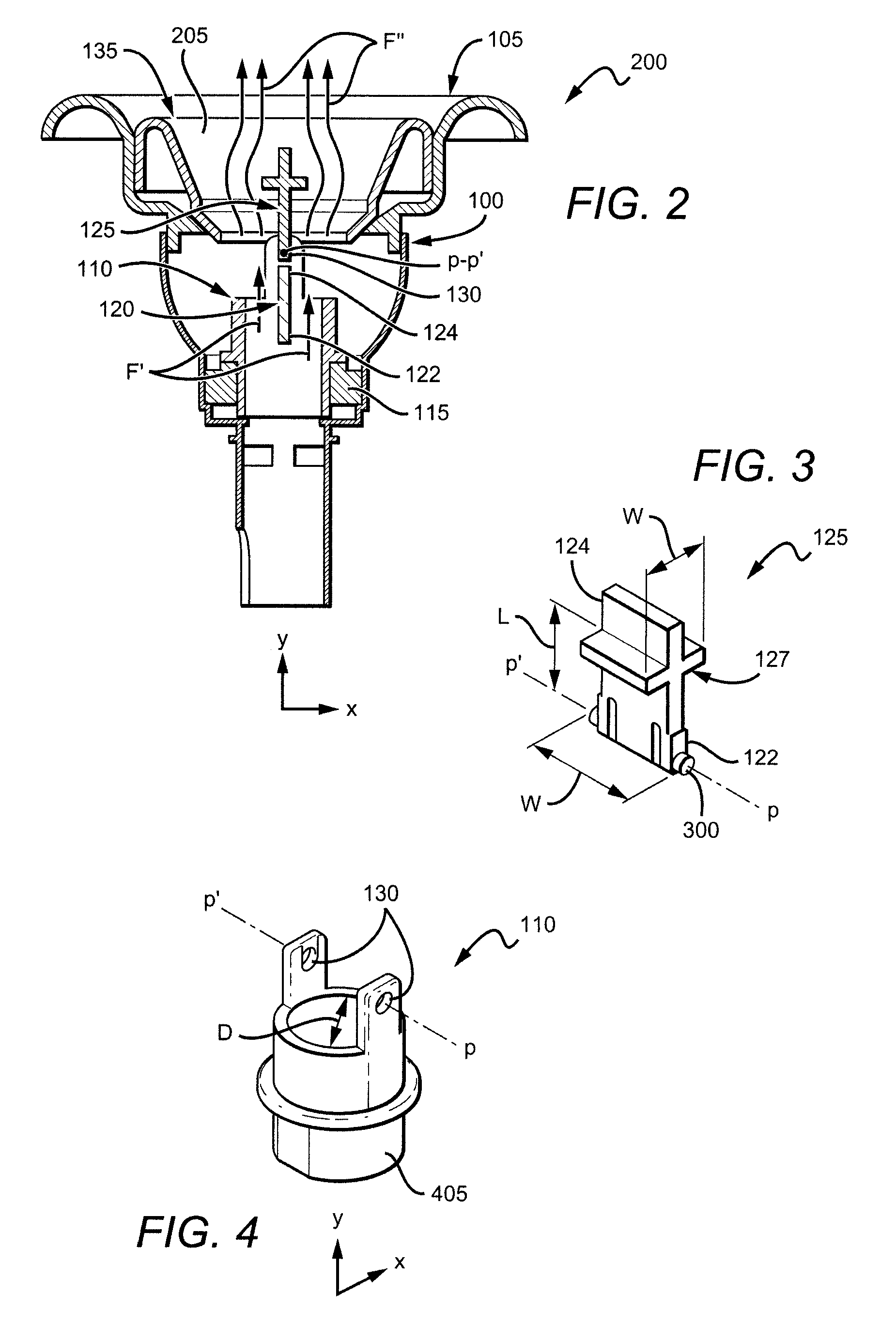
[0019]A hydrotherapy jet, in accordance with one embodiment of the invention, includes a flapper disposed in an internal flow path of a jet body, with the flapper rotatably connected to the jet body to rotatably oscillate in response to water flow to produce a pulsating effect on users positioned downstream of the hydrotherapy jet. The flapper is connected to the jet body at a upstream flapper end, and has a flapper head (alternatively called a “head spoiler”) on a downstream end of the flapper to reduce its oscillation frequency from what would otherwise exist without the flapper head. The flapper, flapper head and jet body are preferably coupled in series with a pump and a plurality of water conduits for use in spas, hot tubs, pools, bathtubs and other tub shells to produce massage effects on users of such systems without additional complexity and cost in comparison to existing fixed jet systems.

[0020]FIG. 1 illustrates one embodiment of the hydrotherapy jet, alternatively called ...


PUM


Abstract

A hydrotherapy jet includes a jet body having an open upstream end and an open downstream end and defining a flow path between the open upstream end and open downstream end, a flapper disposed within the flow path, the flapper having upstream flapper and downstream flapper ends and rotatably connected to the jet body at the upstream flapper end to rotatably oscillate about the upstream flapper end when a stream of water is introduced from upstream to downstream through the flow path and a head spoiler formed on the downstream flapper end to reduce the frequency of oscillation of the flapper wherein a stream of water pulsating effect is felt by a user of the jet apparatus adjacent the open downstream end as the flapper rotatably oscillates.

Description

RELATED APPLICATION[0001]This application claims the benefit of U.S. Provisional Application No. 60 / 854,173, filed Oct. 24, 2006.BACKGROUND OF THE INVENTION[0002]1. Field of the Invention[0003]This invention relates to hydrotherapy jets and more particularly to hydrotherapy jets generating a pulsating water stream.[0004]2. Description of the Related Art[0005]Spas, hot tubs, pools and bathtubs may use water discharge jets to accomplish a variety of pleasing massaging effects for their occupants. Typical jets include a rotating outlet or eyeball, with water flow through the outlet inducing the outlet's rotation to produce a pleasing massaging effect on users. A pulsating effect may also be produced using mechanical blocking devices to intermittently reduce and release a water flow, or using a hydraulic pumping device to distribute water through multiple outlets in front of a rotor. Unfortunately, use of either rotating mechanical or hydraulic pumping devices increases system component...

Claims


Application Information

Patent Timeline
Patent Type & Authority Patents(United States)
IPC IPC(8): A61H7/00
CPCA61H33/6063
Inventor COLIN, RAYMUNDO
Owner B & S PLASTICS
Why Eureka
Try Eureka