
Apparatus and method for magnetically treating fluids

Active Publication Date: 2016-05-19
SPINFLIP
View PDF2 Cites 3 Cited by
  • Summary
  • Abstract
  • Description
  • Claims
  • Application Information

AI Technical Summary

Benefits of technology

The present invention is an apparatus that is designed to improve the combustion properties of fuels and reduce the aggregation of solids in fluids. It consists of two housings with magnets positioned in a non-linear progressive pattern that subjects the fluid or gas being transported to a broad spectrum of magnetic flux. The apparatus also creates a spectrum of magnetic field intensities, vectors, and frequencies that expose the treated fluids to a gauntlet of magnetic forces allowing the appropriate quantum excitation energy and frequency to effect the most efficient fluid treatment process. This has led to improved fuel reactivity, better fuel economy, enhanced performance, and significant reduction in noxious emissions.

Problems solved by technology

However, when treating a broader range of fluids from highly conductive aqueous fluids, to more dielectric fluids and viscous hydrocarbon fuels and oils, it is posited that imposing a magnetic field exclusively orthogonal to the axis of fluid flow does not adequately access or stimulate hydrocarbon molecules that are randomly oriented, folded and clumped and bound by van der Waal forces.

Method used


Image

  • Apparatus and method for magnetically treating fluids
  • Apparatus and method for magnetically treating fluids
  • Apparatus and method for magnetically treating fluids

Examples


Embodiment Construction

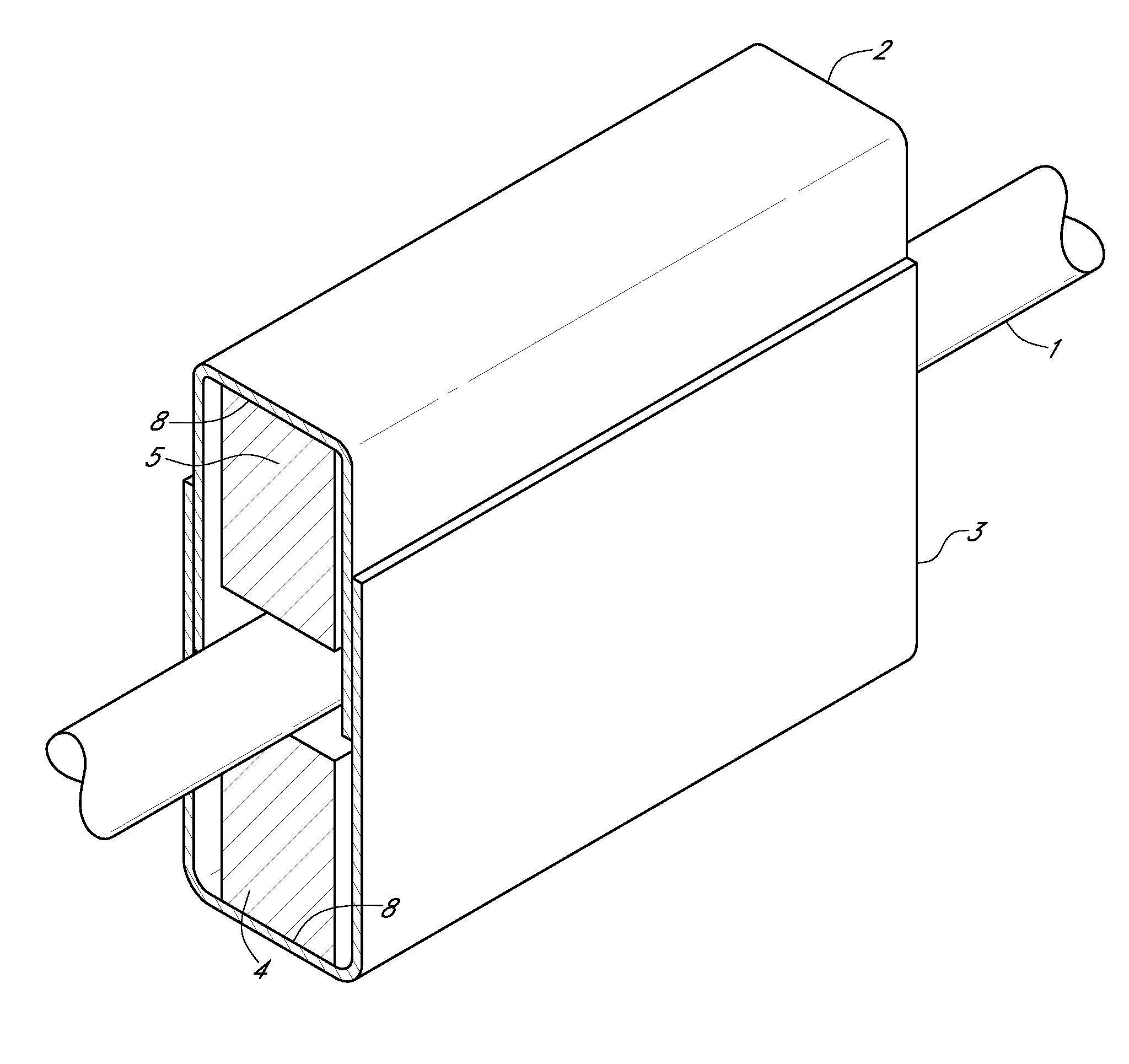
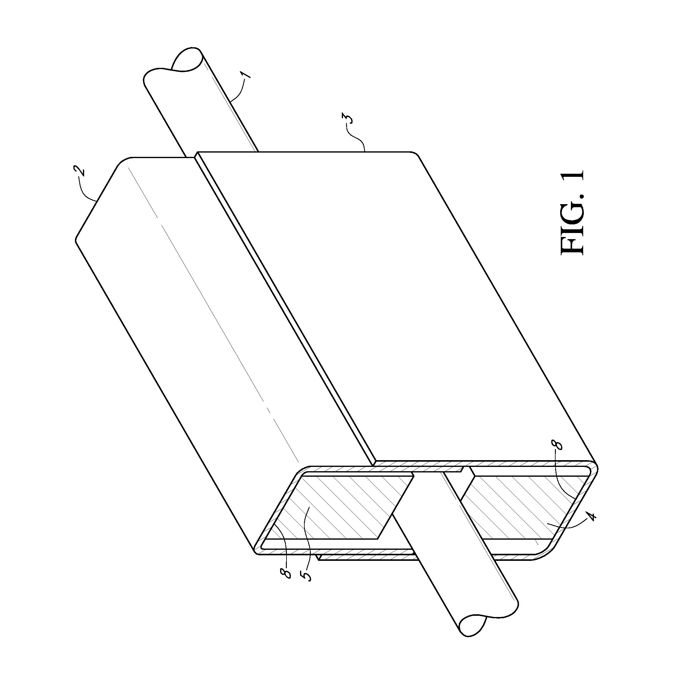
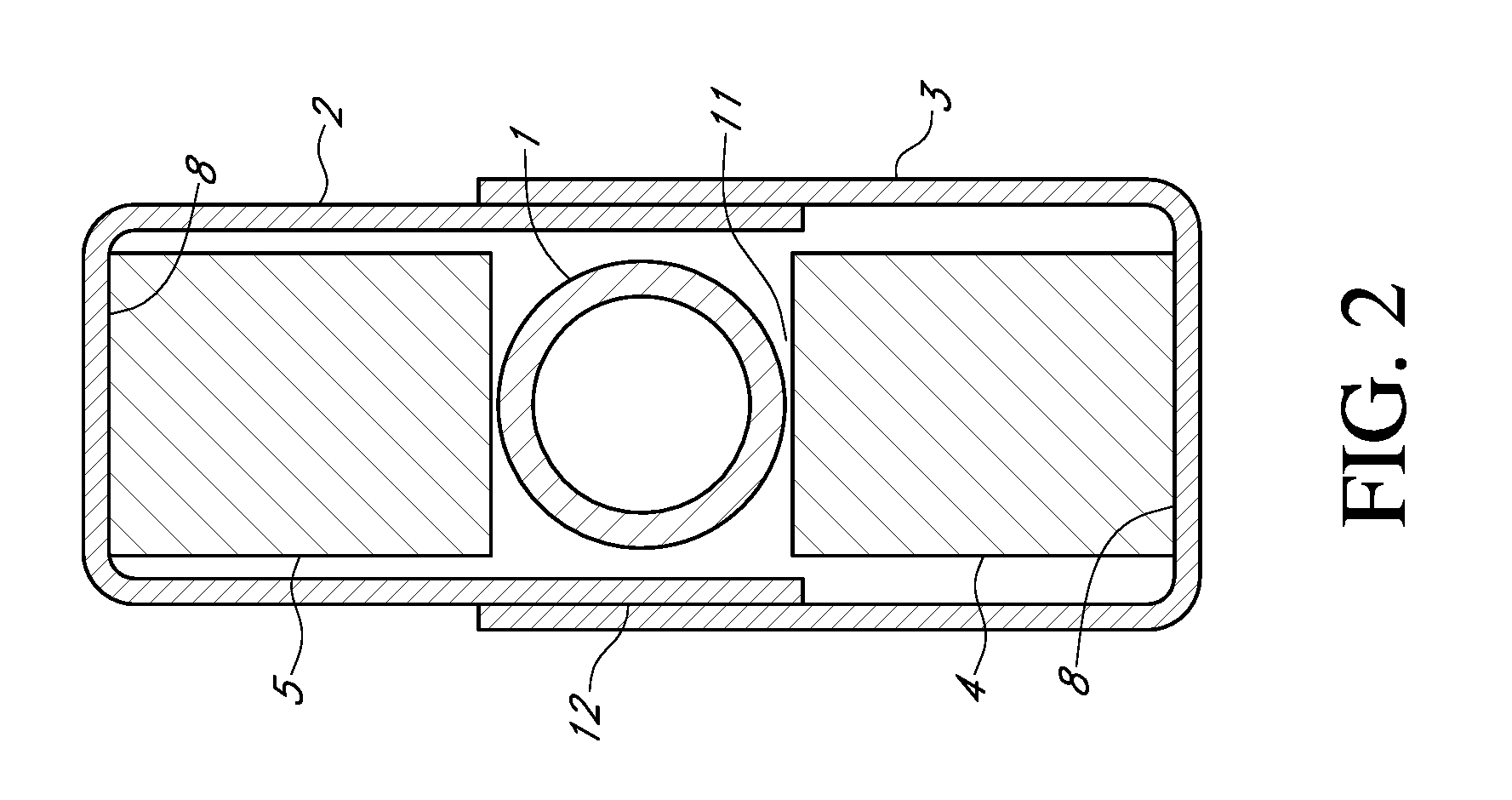
[0034]The invention apparatus shown in FIG. 1 is a magnetic conditioning device which is peripherally attached to a conduit or pipe FIG. 21 through which any gas or fluids may flow. In a particular embodiment, the conduit carries fuels such as gas or diesel in an engine or heating system. The invention comprises two U shape channels, forming Unit half 2 and Unit half 3, that are made of a material, such as metal (and in a particular embodiment, cold rolled steel) sufficient to provide a circuit and magnetically shield the Unit, minimizing the potential for stray fields to interfere with nearby magnetically sensitive devices (in particular computers and sensors in an automobile engine compartment or combustion heating device). The widths of unit half 2 and unit half 3 are slightly different so that the smaller part 2 will slide fit 13 into the larger part 3 with a minimal air gap between the intersecting walls 12 forming a contiguous magnetic shield and a complete magnetic circuit. B...


PUM

PropertyMeasurementUnit
Lengthaaaaaaaaaa
Lengthaaaaaaaaaa
Mechanical propertiesaaaaaaaaaa

Abstract

An apparatus and methodology is presented for magnetically conditioning any hydrocarbon based fluid flowing through a conduit or pipe. The object of the invention is to advance the art by increasing the range of application, the effectiveness, the simplicity and the ease of use of a magnetic fluid conditioning device. The invention accomplishes this by a unique magnetic and mechanical configuration, not taught in the art or previously known to the applicants.

Description

CROSS REFERENCE TO RELATED APPLICATIONS[0001]The present application claims the benefit as a continuation-in-part of U.S. Nonprovisional application Ser. No. 14 / 180,360 filed Feb. 14, 2014 titled “Apparatus and Method for Magnetically Treating Fluids” with Robert E Cox, Oliver H Bodine and William B Cox as joint inventors, which is incorporated herein by reference. The U.S. Nonprovisional application Ser. No. 14 / 180,360 itself claims the benefit of U.S. Provisional Application 61 / 791,940 filed Mar. 15, 2013.FIELD OF THE INVENTION[0002]The field of the present invention generally relates to magnetically conditioning fluids and gases.BACKGROUND OF THE INVENTION[0003]Magnetic water conditioning devices have been used as early as the 1950s (Vermeiren U.S. Pat. No. 2,652,925) for conditioning water in an effort to prevent scale build up and minimize the damaging effects of hard water on pipes. Municipal water supplies and other commonly available water sources often contain a variety of ...

Claims


Application Information

Patent Timeline
IPC IPC(8): C10L1/06F02M27/04C10L1/08B03C1/02
CPCB03C1/02F02M27/045C02F1/482B03C2201/30B03C1/288C10L2290/40C02F1/005C10G32/02
Inventor COX, ROBERT EASTWOODBODINE, OLIVER HAMILTONCOX, WILLIAM BRINTON
Owner SPINFLIP
Learn More