Flow board for fuel cell
- Summary
- Abstract
- Description
- Claims
- Application Information
AI Technical Summary
Benefits of technology
Problems solved by technology
Method used
Image
Examples
Embodiment Construction
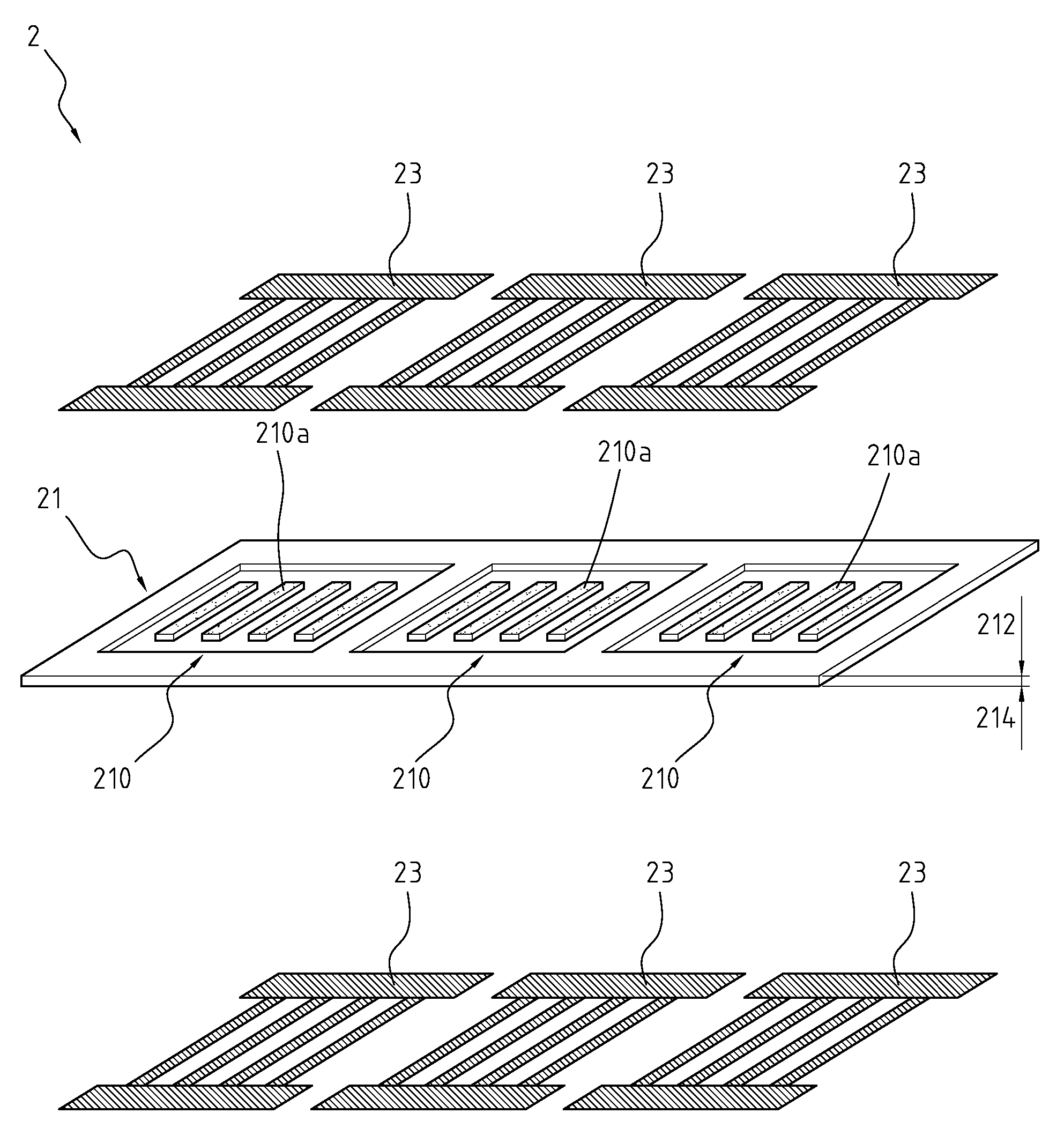
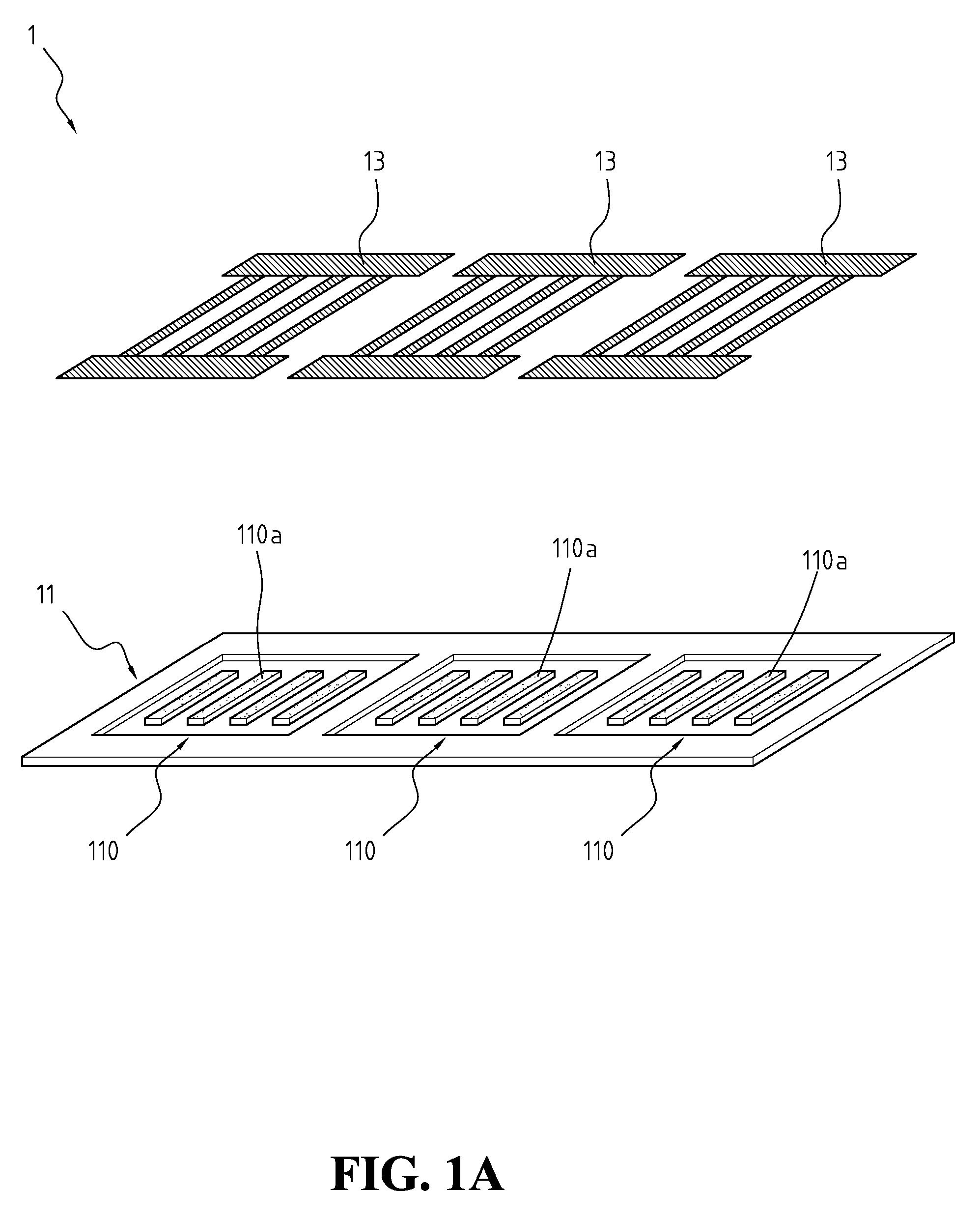
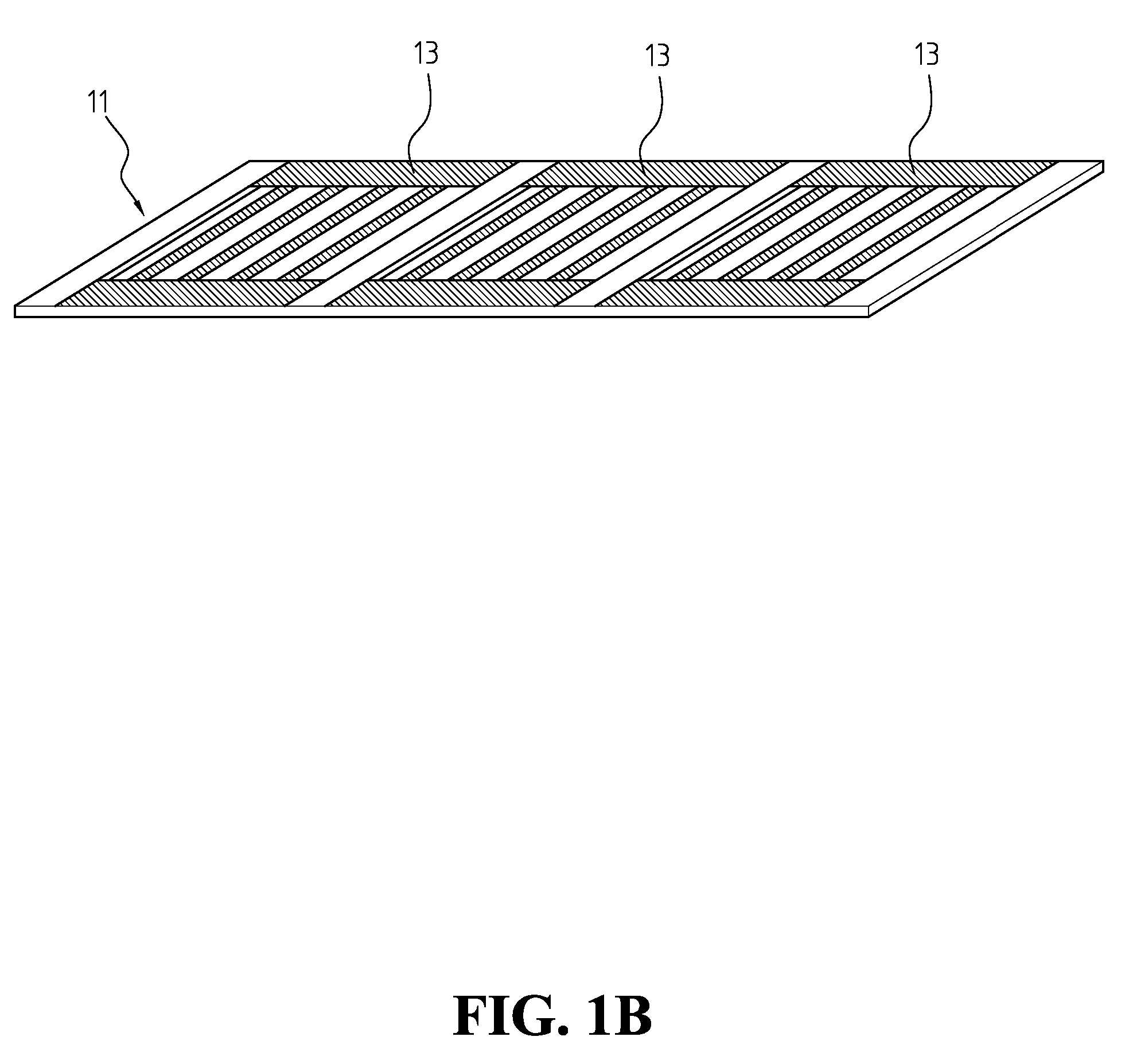
[0017]FIG. 1A is a perspective and exploded diagram of a flow board according to a preferred embodiment of the invention. FIG. 1B is a perspective and associated diagram of FIG. 1A. FIG. 1C illustrates the cross section of FIG. 1B. A flow board 1 capable of collecting current may be applied to a fuel cell that has at least one membrane electrode assembly (MEA). The flow board 1 includes a plate body 11 and one or more current collection sheets 13, which are individually described hereinafter.
[0018] The plate body 11 may adopt a substrate, such as a chemical-resistant non-conductive engineering plastic substrate, a graphite substrate, a metallic substrate, a plastic carbon substrate, or a composite substrate. The plate body 11 is furnished with at least one concave portion 110. The concave portion 110 is formed on the surface of the plate body 11, and each concave portion 110 is disposed corresponding to the position of a MEA (not shows) of a fuel cell. The flow board 1 further incl...
PUM
| Property | Measurement | Unit |
|---|---|---|
| Electrical resistance | aaaaa | aaaaa |
| Current | aaaaa | aaaaa |
Abstract
Description
Claims
Application Information
 - R&D
- Intellectual Property
- Life Sciences
- Materials
- Tech Scout
- Unparalleled Data Quality
- Higher Quality Content
- 60% Fewer Hallucinations
Browse by: Latest US Patents, China's latest patents, Technical Efficacy Thesaurus, Application Domain, Technology Topic, Popular Technical Reports.
© 2025 PatSnap. All rights reserved.Legal|Privacy policy|Modern Slavery Act Transparency Statement|Sitemap|About US| Contact US: help@patsnap.com


