Ganged circulator device

a circulator and ganged technology, applied in coupling devices, waveguide type devices, basic electric elements, etc., can solve the problems of increasing the construction cost of the circulator, achieve the effects of increasing the power level of the circulator, reducing the cost of construction, and improving the efficiency of the circulator

Inactive Publication Date: 2015-11-17
ELECTRONICS RES +1
View PDF2 Cites 0 Cited by
  • Summary
  • Abstract
  • Description
  • Claims
  • Application Information

AI Technical Summary

Benefits of technology

[0011]The present invention provides a ganged circulator device for increasing the circulator's power level, isolation performance, input VSWR performance, and frequency stability. Low power radio frequency circulators have been built for many years using lump constant technology. These types of circulators are small in size and tend to have broad operating characteristics with excellent electrical performance. With the digital broadcasting trend moving towards higher power levels, if used as isolators in analog and digital applications, circulators must handle greater current and voltage levels. With these higher ratings, circulator construction costs escalate. Size increases, but operating bandwidth is reduced. By ganging multiple low power circulators, the present invention provides an inexpensive solution for high power applications.
[0012]A circulator's size also plays a big role in its ability to deliver stable performance. To cope with the heat generated within a circulator from internal resistive loss, circulators are built large in weight and scale. Larger circulators tend to have narrow bandwidth capability. By using small low power circulators ganged together, the present invention overcomes the narrow bandwidth problem.
[0020]The ganged circulator device of the present invention combines both constant impedance operation with high average power handling and high absorption capability. By distributing the applied RF power among parallel connected circulators, the device can tolerate high digital IBOC power levels without failure.

Problems solved by technology

With these higher ratings, circulator construction costs escalate.

Method used


Image

  • Ganged circulator device
  • Ganged circulator device
  • Ganged circulator device

Examples


Embodiment Construction

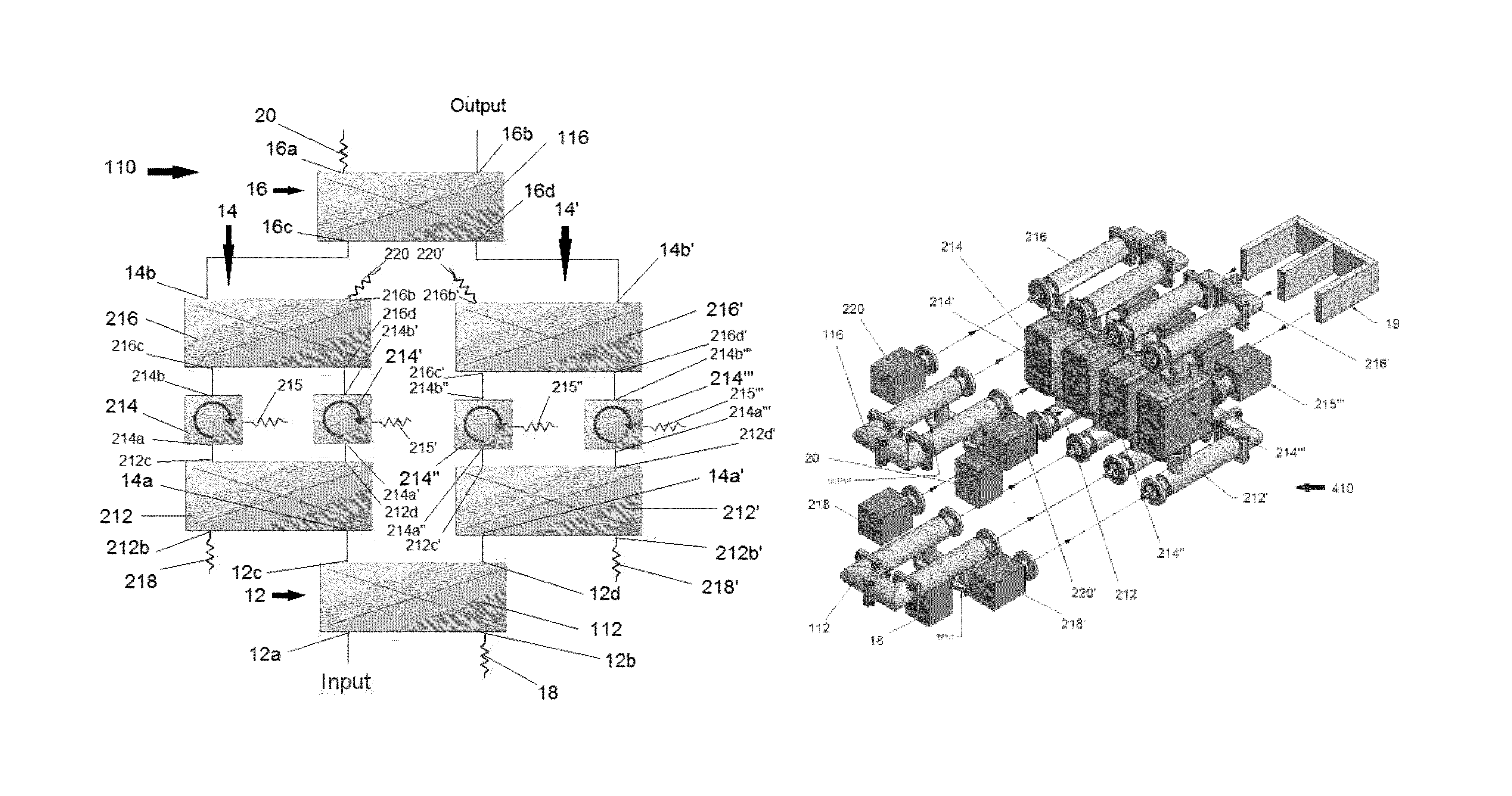
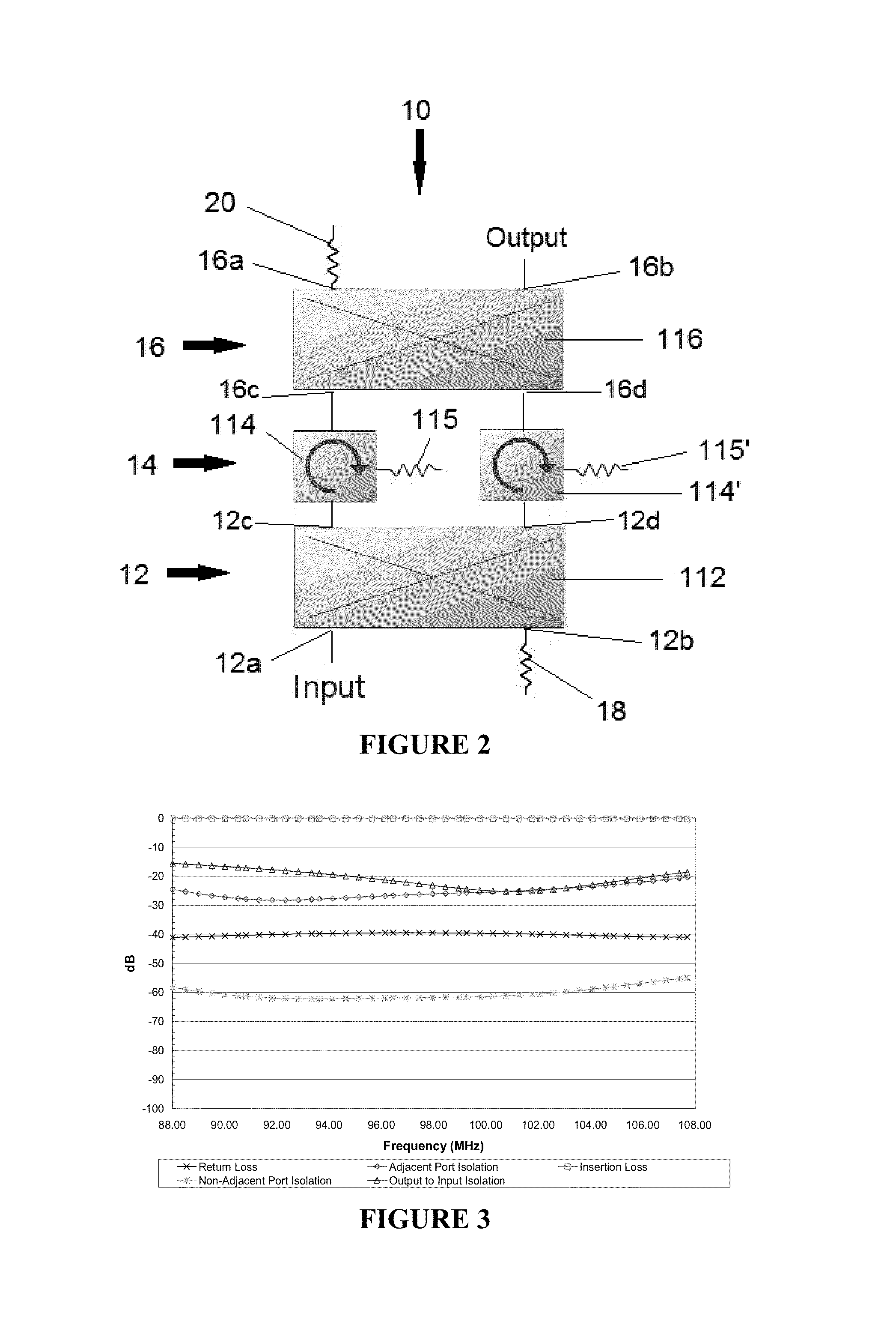
[0036]The present invention utilizes two or more existing circulators and distributes power among them in the form of a Ganged Circulator Device 10. According to the present invention, the Ganged Circulator Device 10 includes three basic components: an input power divider 12, a ganged circulator module 14, and an output power combiner 16. The input power divider 12 includes a first input port 12a, a second input port 12b, and a plurality of output ports, i.e. 12c, 12d. The ganged circulator module 14 includes a plurality of input ports corresponding to and electrically connected to the plurality of output ports on the input power divider 12. The output power combiner 16 includes a first output port 16a, a second output port 16b, and plurality of input ports 16c, 16d corresponding to and electrically connected to a plurality of output ports of the ganged circulator module 14. An input signal may be applied at the first input port 12a of the input power divider 12, and an output signa...


PUM


Abstract

A ganged circulator device for isolating a transmitter and increasing the power level, isolation performance, and input VSWR performance of an IBOC combiner module is provided. The ganged circulator device includes an input power divider, a ganged circulator module, and an output power combiner. The input power divider includes a first input port, a second input port, and a plurality of output ports. The ganged circulator module includes a plurality of circulators and a plurality of load resistors. The module also includes input ports corresponding to and electrically connected to the plurality of output ports on the input power divider. The output power combiner includes a first output port, a second output port, and plurality of input ports corresponding to and electrically connected to a plurality of output ports of the ganged circulator module. An input signal is applied at the first input port of the input power divider, and an output signal is transmitted from the second output port of the power combiner. A first load resistor is electrically connected to the second input port of the power divider, and a second load resistor is connected to the first output port of the power combiner.

Description

FIELD OF THE INVENTION[0001]The present invention relates to devices that provide transmitter-to-transmitter isolation and isolation from a system, such as an antenna or group of stations operating in a multiplexed system through the use of parallel low power circulators. More specifically, the present invention relates to improved power handling, temperature stability, isolation performance, and input VSWR performance of a single circulator.BACKGROUND OF THE INVENTION[0002]The standard master antenna dual-input RF system is typically designed for use by multiple radio stations operating both digital and analog transmitters. The antenna is typically provided with two wide-band ports, one designated analog and the other digital for combining in the antenna. Each station is provided its own analog or analog and digital IBOC (in-band-on-channel) combiner module to restrict transmitter-to-transmitter interference.[0003]In single antenna input configurations, the multiplexing of combiner...

Claims


Application Information

Patent Timeline
Patent Type & Authority Patents(United States)
IPC IPC(8): H01P1/38H01P5/16
CPCH01P1/38H01P5/16
Inventor ROSE, ROBERT W.PAULIN, NICHOLAS A.
Owner ELECTRONICS RES
Why Eureka
Try Eureka