
Phase-change memory element driver circuits using measurement to control current and methods of controlling drive current of phase-change memory elements using measurement

Inactive Publication Date: 2005-12-22
SAMSUNG ELECTRONICS CO LTD
View PDF8 Cites 37 Cited by
  • Summary
  • Abstract
  • Description
  • Claims
  • Application Information

AI Technical Summary

Benefits of technology

[0016] In particular embodiments of the present invention, the detection circuit comprises a voltage detection circuit. The voltage detection circuit may be configured to compare the measured voltage of the data line and a reference voltage and output a control signal based on whether the measured voltage is greater than or less than the reference voltage. The controller circuit may include a current mirror circuit configured to increase an amount of current supplied to the phase-change memory cell until the control signal output by the voltage detection circuit indicates that the measured voltage is less than the reference voltage and maintain the amount of current supplied to the phase-change memory cell when the control signal output by the voltage detection circuit indicates that the measured voltage is less than the reference voltage.

Problems solved by technology

However, the programming section, 2, is non-linear.
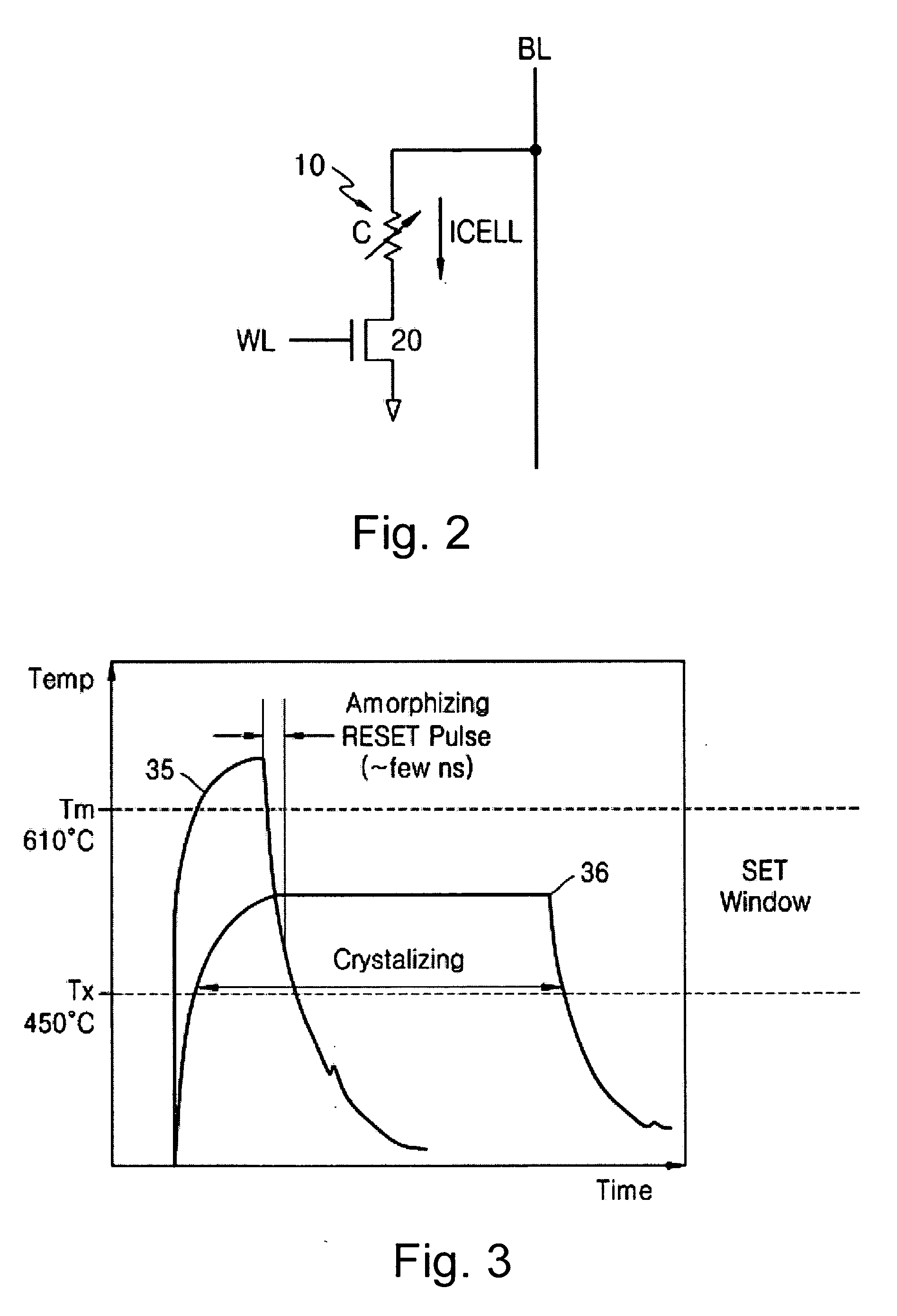
Such a change in voltage may be problematic where the different memory cells have different threshold voltages and may cause some cells to not be set if the same current is applied to all the cells as the voltage may not reach the threshold voltage, reduction of reset current may also cause difficulty in fitting the set current into the narrowed set window and it may be difficult to maintain the voltage and / or current in the set window as illustrated in FIG. 5B for all of the devices.

Method used


Image

  • Phase-change memory element driver circuits using measurement to control current and methods of controlling drive current of phase-change memory elements using measurement
  • Phase-change memory element driver circuits using measurement to control current and methods of controlling drive current of phase-change memory elements using measurement
  • Phase-change memory element driver circuits using measurement to control current and methods of controlling drive current of phase-change memory elements using measurement

Examples


Embodiment Construction

[0032] The present invention now will be described more fully hereinafter with reference to the accompanying drawings, in which embodiments of the invention are shown. However, this invention should not be construed as limited to the embodiments set forth herein. Rather, these embodiments are provided so that this disclosure will be thorough and complete, and will fully convey the scope of the invention to those skilled in the art. In the drawings, the thickness of layers and regions are exaggerated for clarity. Like numbers refer to like elements throughout. As used herein the term “and / or” includes any and all combinations of one or more of the associated listed items.

[0033] The terminology used herein is for the purpose of describing particular embodiments only and is not intended to be limiting of the invention. As used herein, the singular forms “a”, “an” and “the” are intended to include the plural forms as well, unless the context clearly indicates otherwise. It will be furt...


PUM


Abstract

Programming phase-change memory devices and driver circuits for programming phase-change memory devices are provided that control an amount of current supplied to a phase-change material of the phase-change memory device based on a measure of resistance of the phase-change material during programming of the phase-change memory device. Such control may be based on detected voltage or current. The amount of current supplied to the phase-change material may be increased until the measured voltage level changes with respect to a reference voltage value and the current maintained constant if the measured voltage level has changed with respect to the reference voltage value. The change of the measured voltage level with respect to the reference voltage may be the measured voltage level falling below the reference voltage value.

Description

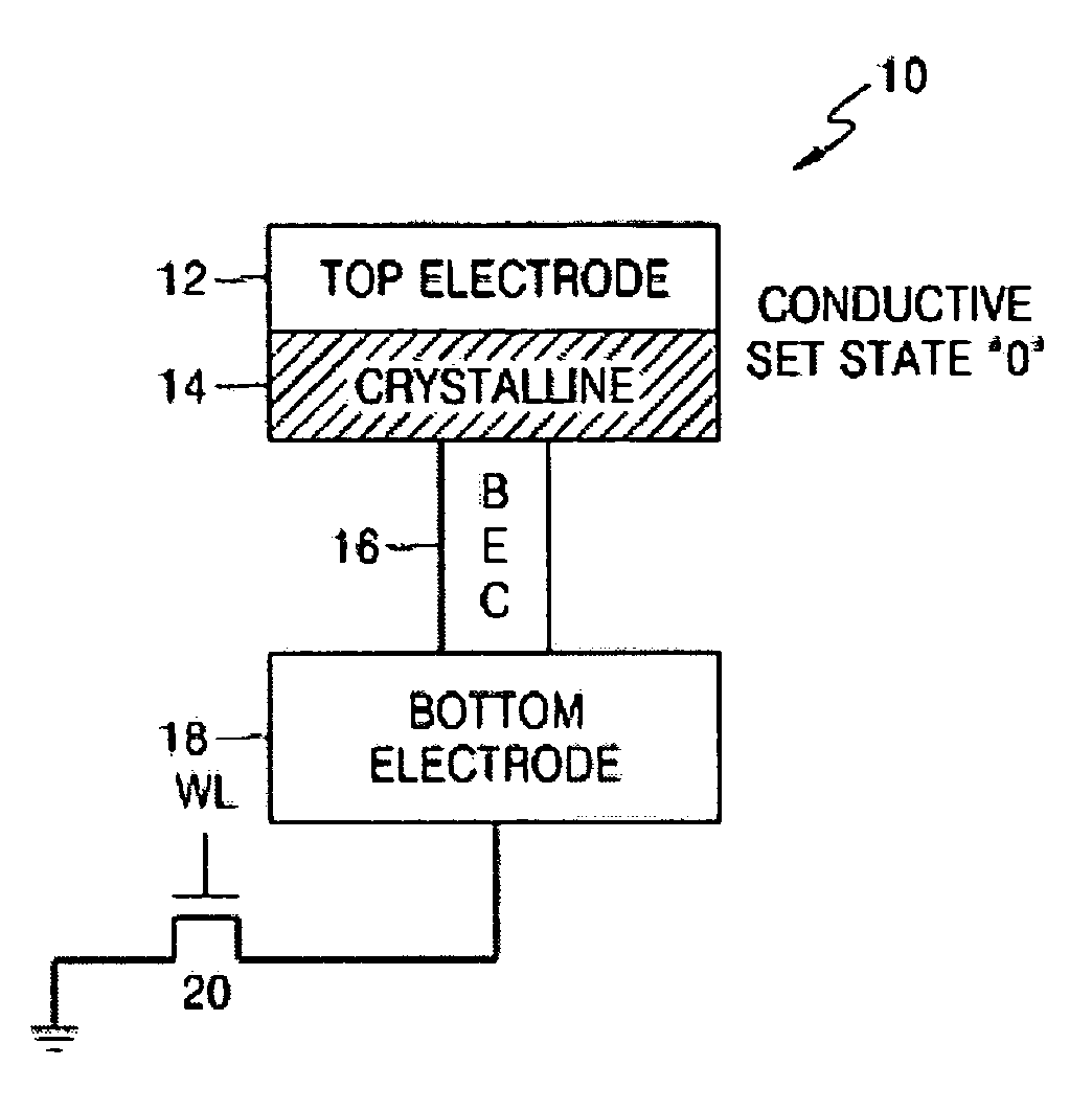
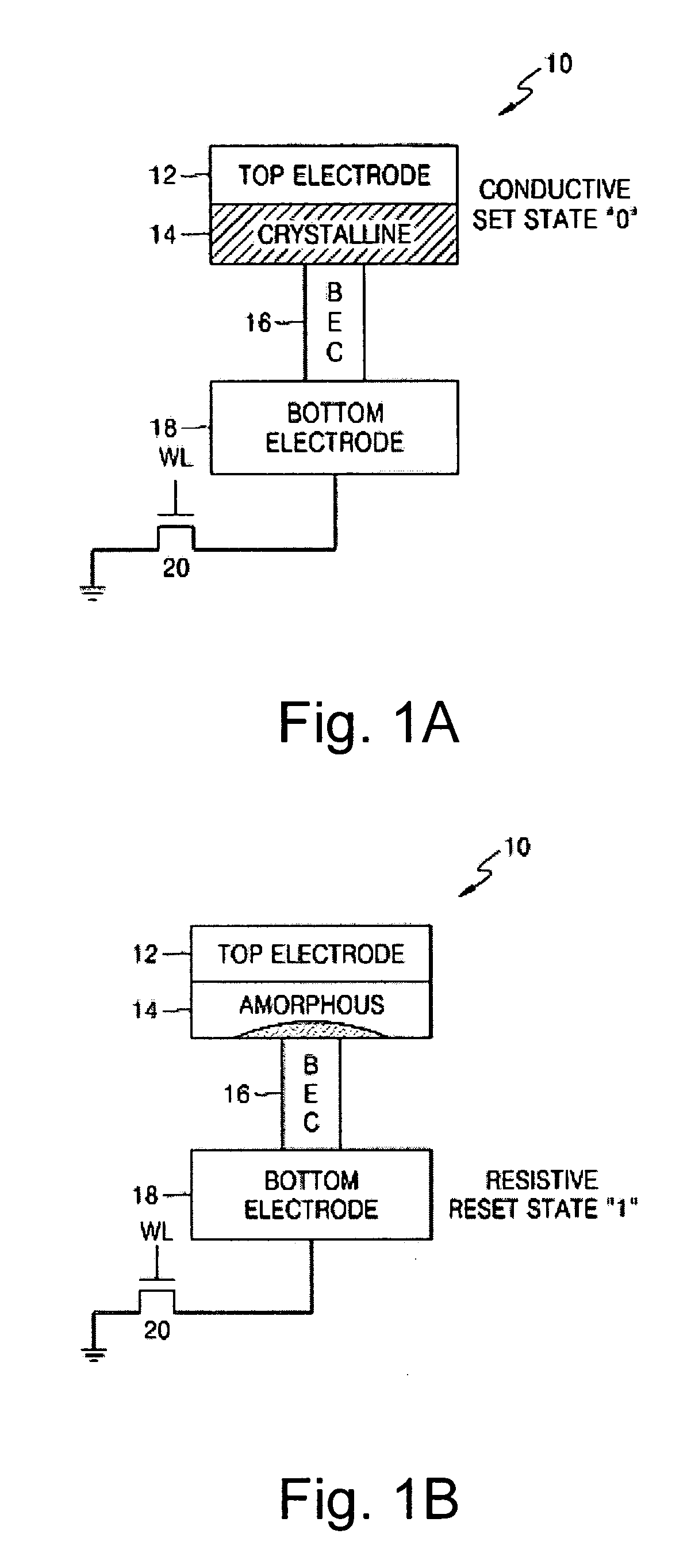
RELATED APPLICATIONS AND CLAIM OF PRIORITY [0001] This application is related to and claims priority from Korean Patent Application No. 2004-45849, filed on Jun. 19, 2004, in the Korean Intellectual Property Office, the disclosure of which is incorporated by reference herein in its entirety. FIELD OF THE INVENTION [0002] The present invention relates to driver circuits for memory elements, and more particularly, to driver circuits and / or methods for phase-change memory elements. BACKGROUND OF THE INVENTION [0003] A phase-change memory element is a memory element for storing information using the characteristics of electric conductivity or a resistance difference between a crystalline phase and an amorphous phase of a specific phase-change material. The phase-change memory element forms a memory cell electrically connected to a transistor element or the like, formed on a semiconductor substrate for addressing and read / write operations of the device. In the memory element, information...

Claims


Application Information

Patent Timeline
IPC IPC(8): G11C13/02G11C11/00G11C16/02
CPCG11C13/0004G11C13/0064G11C2213/79G11C2013/0078G11C13/0069G11C13/02
Inventor CHO, WOO-YEONGKANG, SANG-BEOM
Owner SAMSUNG ELECTRONICS CO LTD
Learn More