
Application specific integrated circuitry for controlling analysis of a fluid

a technology of integrated circuits and fluids, applied in the field of fluid sensors, can solve the problems of cumbersome and time-consuming process, inability to sense fluid characteristics, and currently sensing technology, although able to sense some fluid characteristics, may not suffice in a commercial environment wher

Inactive Publication Date: 2005-03-29
MEAS FRANCE
View PDF32 Cites 44 Cited by
  • Summary
  • Abstract
  • Description
  • Claims
  • Application Information

AI Technical Summary

Benefits of technology

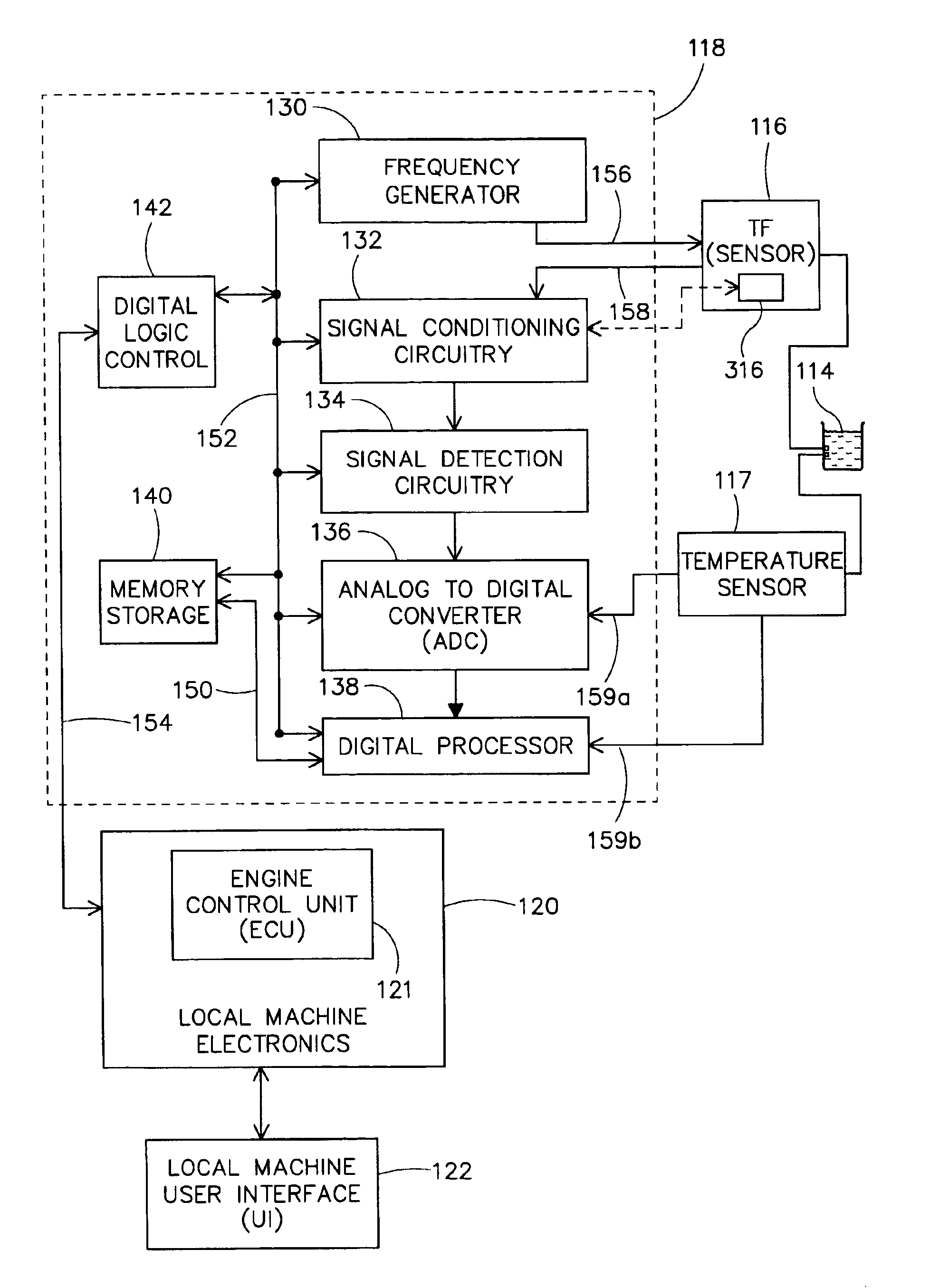
In another embodiment, a circuit for determining characteristics of a fluid under-test is provided. The circuit includes analog-to-digital processing circuitry for interfacing with a sensor and host electronics. The analog-to-digital processing circuitry includes a frequency generator for providing stimulus to the sensor and receiving a response signal from the sensor. Conditioning circuitry for reducing analog signal offsets in the response signal and signal detection circuitry for identifying phase and amplitude data of the response signal are provided. Further provided is analog-to-digital conversion circuitry for converting the detected phase and amplitude data into digital form. Memory for holding calibration data and approximated fluid characteristics of the fluid under-test is included in the circuitry. The digital form of the response signal is processed in conjunction with the calibration data and approximated fluid characteristics to generate fluid characteristics of the actual fluid under-test.

Problems solved by technology

As can be appreciated, this process, although computer assisted, is cumbersome and time consuming.
Therefore, currently sensing technology, although able to sense some fluid characteristics, may not suffice in a commercial environment where on-the-fly or real-time in-situ measurements, analysis and feedback is needed.

Method used


Image

  • Application specific integrated circuitry for controlling analysis of a fluid
  • Application specific integrated circuitry for controlling analysis of a fluid
  • Application specific integrated circuitry for controlling analysis of a fluid

Examples


Embodiment Construction

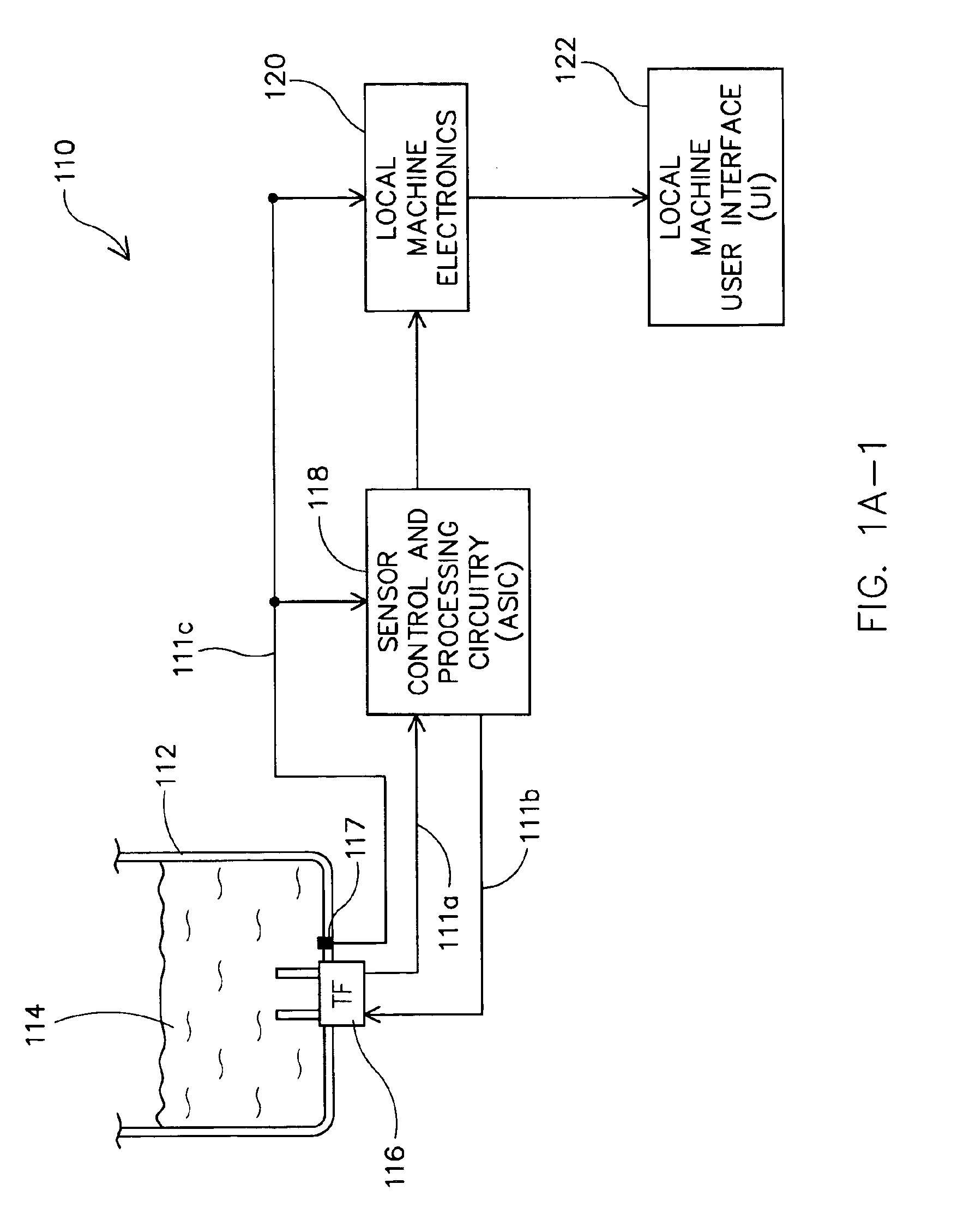
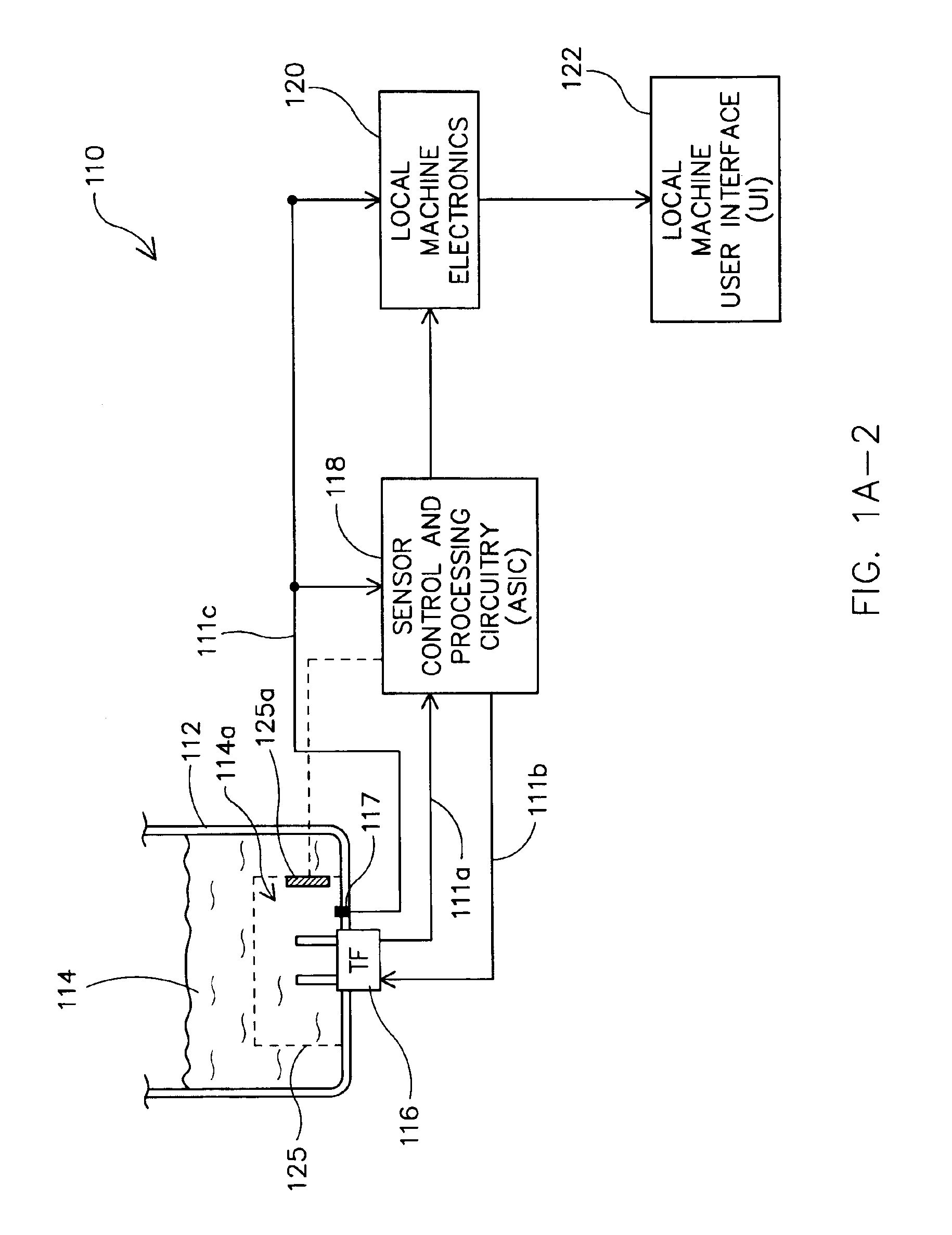
An invention is disclosed for an application specific integrated circuit (ASIC) that is used to interface with a fluid sensor to determine characteristic conditions of the fluid being sensed. As used herein, the fluid being sensed will be referred to as a “fluid under-test.” Although specifics are provided with regard to engine oil, as the fluid under-test, it should be understood that any fluid capable of being sensed to ascertain its characteristics (e.g., chemical components or physical attributes) can utilize the teachings defined herein. For instance, the term “fluid” should be broadly construed to included any material in either a liquid form, gas form, a solid form, or a combination of any one of liquid, gas or solid.

Accordingly, in the following description, numerous specific details are set forth in order to provide a thorough understanding of the present invention. It will be apparent, however, to one skilled in the art that the present invention may be practiced without s...


PUM


Abstract

A circuit for determining characteristics of a fluid under-test is provided. The circuit includes analog-to-digital processing circuitry for interfacing with a sensor and host electronics. The analog-to-digital processing circuitry includes a frequency generator for providing stimulus to the sensor and receiving a response signal from the sensor. Conditioning circuitry for reducing analog signal offsets in the response signal and signal detection circuitry for identifying amplitude data of the response signal are provided. Further provided is analog-to-digital conversion circuitry for converting the detected amplitude data into digital form. Memory for holding calibration data and approximated fluid characteristics of the fluid under-test is included in the circuitry. The digital form of the response signal is processed in conjunction with the calibration data and approximated fluid characteristics to generate fluid characteristics of the actual fluid under-test.

Description

BACKGROUND OF THE INVENTION1. Field of the InventionThe present invention generally relates to fluid sensors, and more particularly to specialized circuitry for interfacing with a fluid sensor to enable control and monitoring of the fluid sensor to generate characterizing data for a fluid.2. Description of the Related ArtIn the art of fluid analysis, there exists a number of techniques for determining the characteristics of a fluid. In the case of fluids used in machines, such as automobiles, engines, and the like, there has been much experimentation in fluid analysis. For instance, a machine commonly requires specific fluids, and some are used to lubricate components of the machine. As is well known, one such fluid is engine oil, which is used to lubricate critical parts that would otherwise be damaged due to their continuous frictional movement.To understand the state of a fluid at a particular point in time, sensors have been used to quantify characteristics of the fluid. Such se...

Claims


Application Information

Patent Timeline
IPC IPC(8): G01L7/00G01N31/00G06F19/00G01N29/036G01N29/34G01N29/36
CPCG01N29/036G01N29/34G01N29/36G01N2291/0427G01N2291/02818
Inventor KOLOSOV, OLEG V.MATSIEV, LEONIDSPITKOVSKY, MIKHAIL B.GAMMER, VLADIMIR
Owner MEAS FRANCE
Learn More