

Expansion bridge apparatus and method for an I2C bus
a technology of expansion bridge and expansion bridge, applied in the field of electronic equipment, can solve problems such as the practicability limit of closer to 1-8 devices
- Summary
- Abstract
- Description
- Claims
- Application Information
AI Technical Summary
Benefits of technology
Problems solved by technology
Method used
Image

Examples
Embodiment Construction
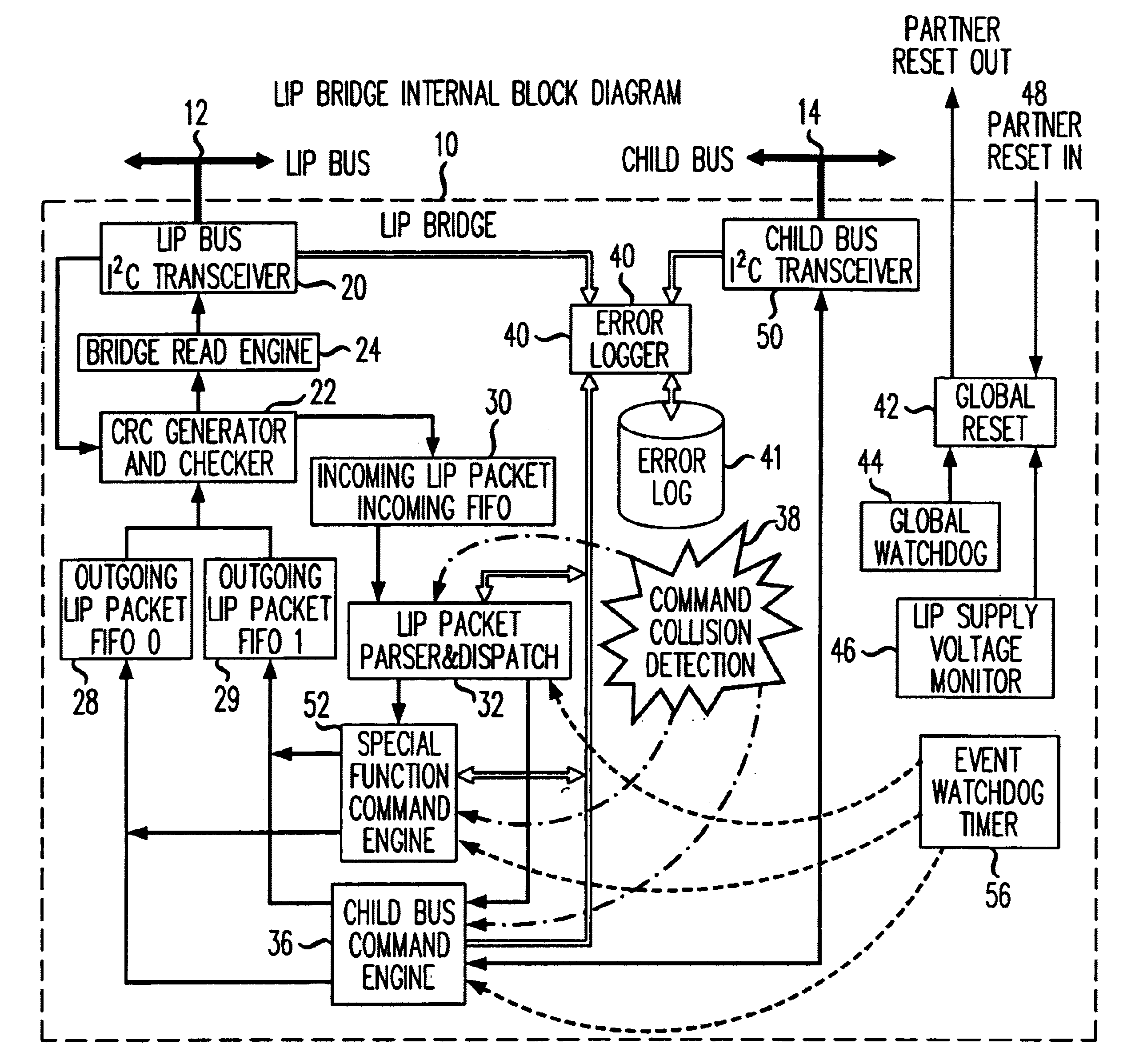
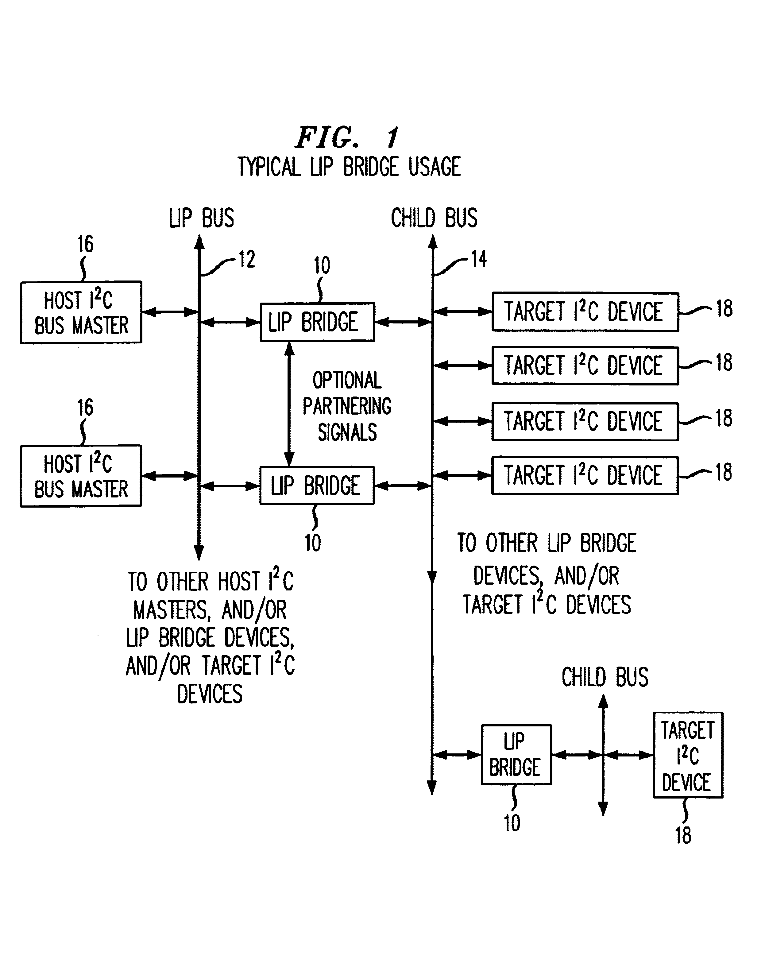
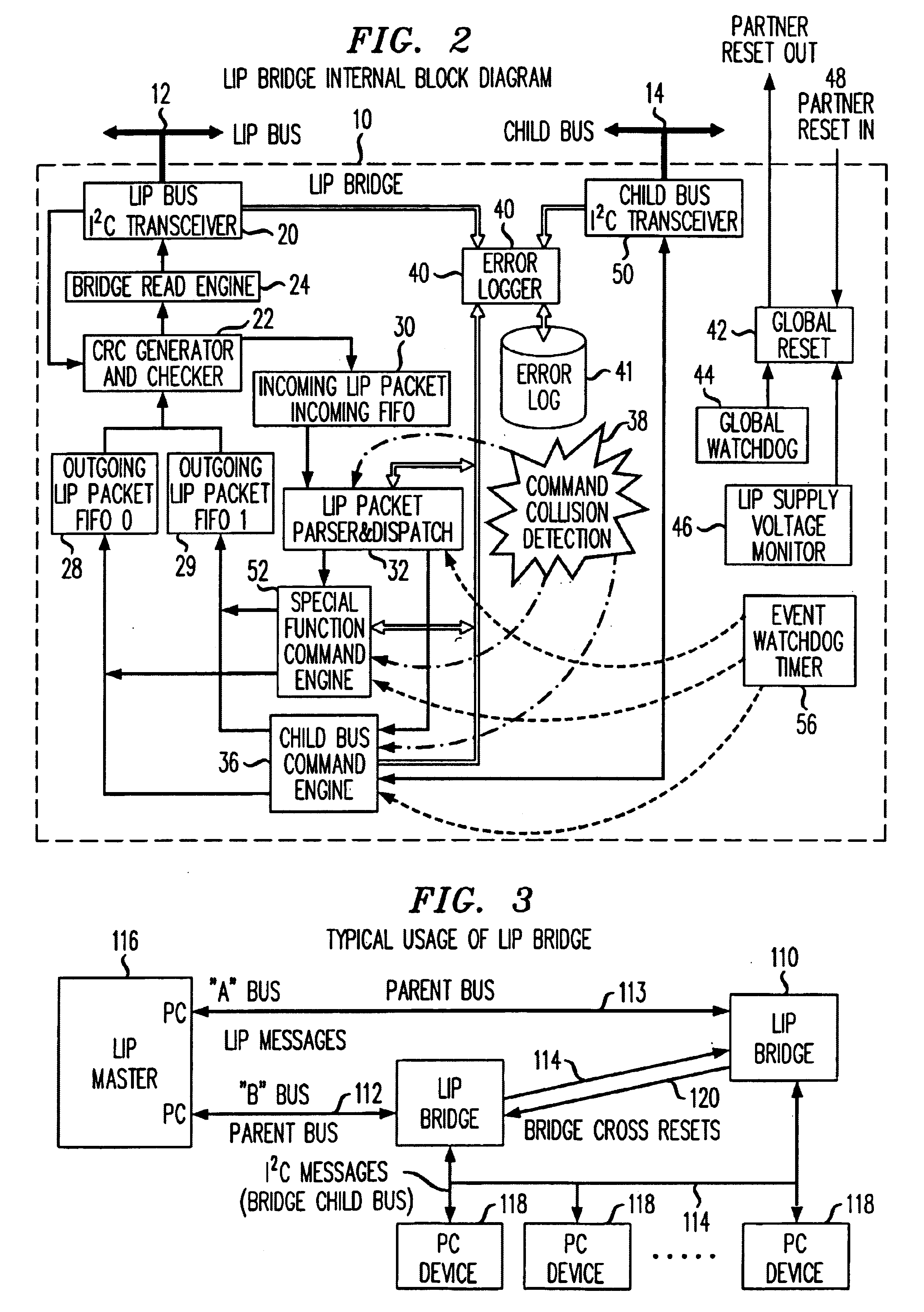
The present invention is an I2C (inter-IC control) bridge device which implements a communication protocol layered on top of a standard I2C protocol. The layered protocol used by the bridge device is termed the “Layered I2C Protocol”—abbreviated “LIP”. Thus the bridge device is called a “LIP bridge device”. The LIP bridge device provides I2C address extension, data integrity checking, and fault detection and isolation when inserted between an I2C bus master and it's intended target I2C device. Referring to FIG. 1, an illustration of a typical usage of the LIP bridge device 10 is shown. Each LIP bridge device has at least two attached I2C busses—a parent bus 12 and a child bus 14. The LIP bridge device 10 can have more than one child bus or parent bus port. The LIP bridge 10 operates as a slave on its parent bus 12, and a master of its child bus 14. The Layered I2C protocol is specified to operate on a bus between one or more bus masters 16 and the parent bus of one or more LIP bridg...
PUM
 Abstract
Description
Claims
Application Information