
Multi-tasking utility tool

a multi-tasking, utility tool technology, applied in the direction of manufacturing tools, portable power-driven tools, wrenches, etc., can solve the problems of knife blades that are very sharp and therefore dangerous, knives that cannot be withdrawn, and knives that cannot be used

Inactive Publication Date: 2005-04-05
WAMPUN +1
View PDF27 Cites 34 Cited by
  • Summary
  • Abstract
  • Description
  • Claims
  • Application Information

AI Technical Summary

Benefits of technology

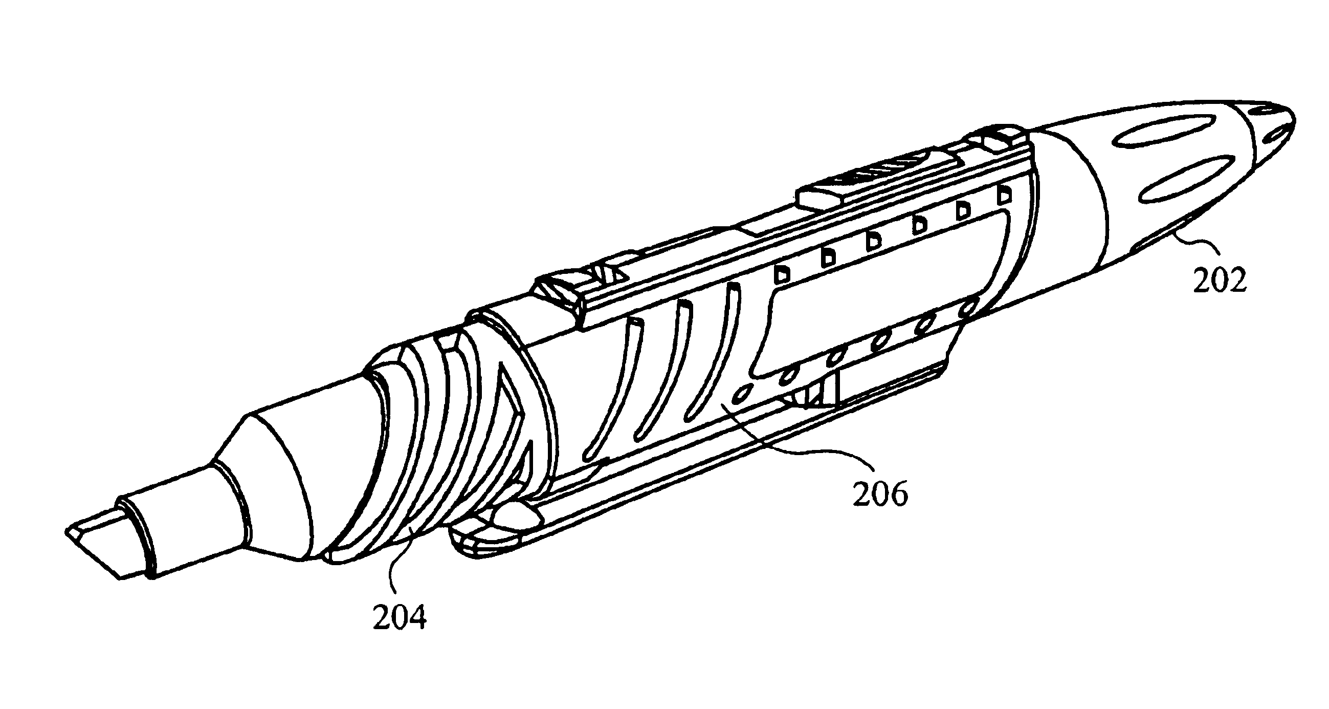
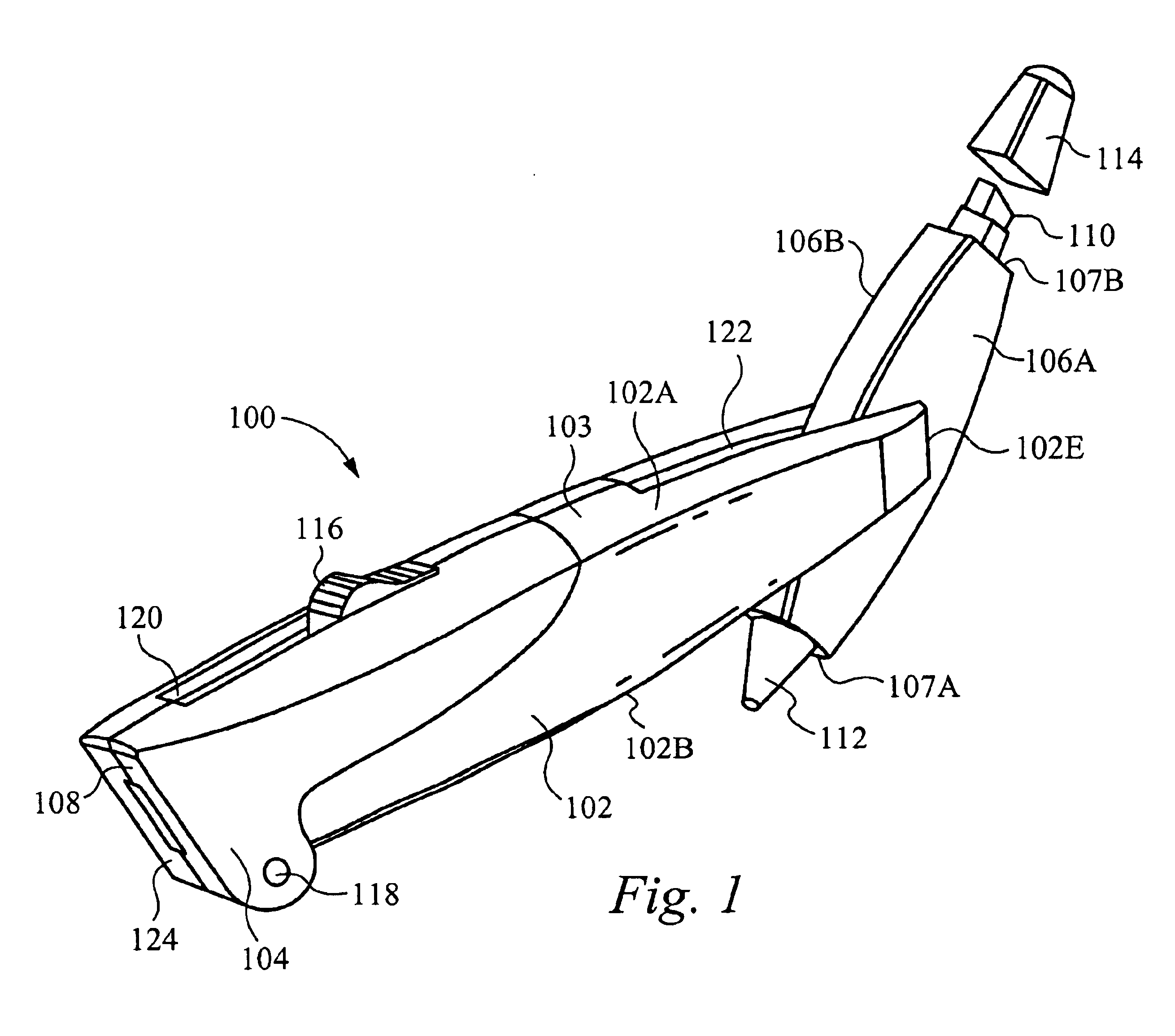
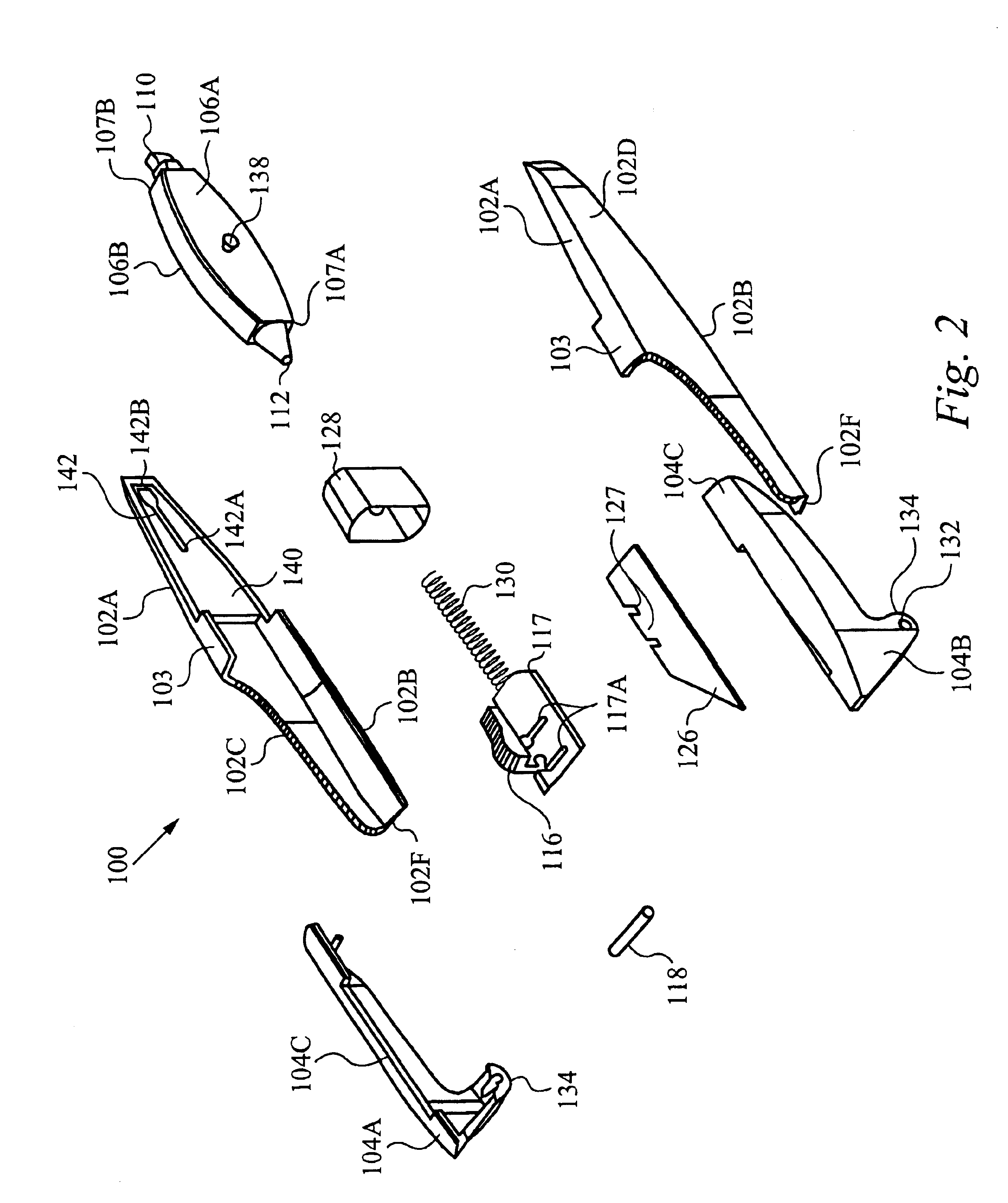
In yet another aspect, a removable blade cartridge that is configured to fit within a corresponding blade cartridge bay. The blade cartridge comprises a blade cartridge body that has a recess slot within and a knife blade slot that is in communication with the recess slot. The cartridge includes a knife blade that is positionable within the recess and is configured to slidably move between an open position and a closed position. The cartridge includes a guide assembly that is coupled with the knife blade, wherein the guide assembly drives the knife blade between the closed position and the open position. The cartridge includes a leaf member for engaging and disengaging the blade cartridge to the blade cartridge bay. The blade cartridge body further comprises a first blade member and a second blade member. The second blade member is in communication and is positioned substantially parallel to the first blade member. The recess slot is located between the first blade member and the second blade member. The blade cartridge body includes a thin film of material that is configured over the knife slot such that the knife blade pierces the thin film when moving initially from the closed position to the open position. The bay cartridge bay further comprises a guide spring

Problems solved by technology

Although box cutting knives are very popular, the knife blade is very sharp and therefore dangerous.
Box cutting knives do not have a safety mechanism which automatically causes the knife to retract within the body of the cutting tool when not in use.
Thus, a user may easily cut herself if not paying attention to the knife blade.

Method used


Image

  • Multi-tasking utility tool
  • Multi-tasking utility tool
  • Multi-tasking utility tool

Examples


Embodiment Construction

Reference will now be made in detail to the preferred and alternative embodiments of the invention, examples of which are illustrated in the accompanying drawings. While the invention will be described in conjunction with the preferred embodiments, it will be understood that they are not intended to limit the invention to these embodiments. On the contrary, the invention is intended to cover alternatives, modifications and equivalents, which is included within the spirit and scope of the invention as defined by the appended claims. Furthermore, in the following detailed description of the present invention, numerous specific details are set forth in order to provide a thorough understanding of the present invention. However, it should be noted that the present invention is able to be practiced without these specific details. In other instances, well known methods, procedures and components have not been described in detail as not to unnecessarily obscure aspects of the present inven...


PUM


Abstract

A utility tool comprising a body having a first end and a second end positioned on opposite ends of the body; a removable blade cartridge positioned within the body, wherein a knife blade within the removable blade cartridge is configured to slidably extend out from the first end; as well as a first tool and a second tool configured to be selectively coupled to each other or one of either the first end and second end of the body. The utility tool includes a knife switch coupled to the knife blade, the knife blade moves from the retracted position to the extended position only when the blade cartridge is engaged within the body. The utility tool having a spring mechanism for biasing the knife blade to the retracted position and a leaf member for engaging and disengaging the blade cartridge from the blade cartridge bay by a snap fit.

Description

FIELD OF THE INVENTIONThe present invention relates to the field of hand held tools. More specifically, the present invention relates to the field of a multi-tasking tool having a replaceable knife blade cartridge and replaceable capsuled instruments.BACKGROUND OF THE INVENTIONIn the existing world of tools many different types of cutting tools are available. One of these cutting tools is a box cutting tool or an Exacto knife. The knife portion in the box cutting knife is sufficiently sharp such that the knife will easily cut through material. Therefore, many carpenters and tool users mark where the material is to be cut before using the Exacto knife to cut the material. Also, when using such a knife to open boxes, a writing instrument is useful to input markings on the box regarding the contents of the box. Thus, the user must keep a pen or marker nearby when using a box cutting knife. Although box cutting knives are very popular, the knife blade is very sharp and therefore dangero...

Claims


Application Information

Patent Timeline
IPC IPC(8): B26B5/00B26B11/00B26B9/00B43K29/18
CPCB26B5/001B26B5/003B26B11/008B26B11/00B26B9/00
Inventor JOHNSON, RONALD L.HEBERT, RAPHAEL VINCENTMANSOURI-CHAFIK, IDRISS
Owner WAMPUN
Learn More