Wiper blade for windows of motor vehicles

a technology for windows and motor vehicles, applied in vehicle maintenance, vehicle cleaning, domestic applications, etc., can solve the problems of inability to properly wipe, reduce contact pressure, and build up of negative pressur

Inactive Publication Date: 2005-04-05
ROBERT BOSCH GMBH
View PDF14 Cites 80 Cited by
  • Summary
  • Abstract
  • Description
  • Claims
  • Application Information

AI Technical Summary

Benefits of technology

It is therefore an object of the present invention to provide a wiper blade for windows of motor vehicles, which avoids the disadvantages of the prior art.
In the wiper blade, via the leading-edge face that faces into the wind, a force component aimed at the window is built up, which counteracts the liftoff tendency of the two pressures and thus assures excellent cleaning quality, at least in the region of the swept field swept by the wiper blade, that is, the region that is important to the vehicle's driver. Depending on the size of the leading-edge face and / or on the size of the approach angle α, this auxiliary contact pressure can be adapted to the variable demands that depend on the type of the vehicle. It is also advantageous in the arrangement of the invention that as a function of the vehicle speed, the contact pressure rises or falls with this speed. Thus a suitably great “auxiliary contact pressure” is opposed only to the liftout tendency that occurs at high speed.
An especially simple, economical realization of the leading-edge face is obtained if the leading-edge face is disposed on the wiper strip.
The flexibility of the wiper strip with regard to a plane vertical to a plane defined by a convex upper side is not impaired, or is impaired only insignificantly, if the projection comprises a material different from, and in particular softer than, the sweeper strip. Under some circumstances it may be expedient to select a harder material for the projection, to increase the stability of the wiper blade.

Problems solved by technology

On the other hand, on the back side facing away from the wind, because of the structural form noted above, a considerable negative pressure builds up.
At relatively high vehicle speeds, given the cooperation of these two aforementioned pressures, both of which are oriented counter to the wiper blade contact pressure, this contact pressure is reduced at least enough that proper wiping is no longer possible.
Increasing the wiper blade contact pressure against the window at high vehicle speeds could admittedly reduce the severity of this problem, but at lower vehicle speeds, when the liftoff tendency is less, the friction between the wiper blade and the window increases; this leads to undesirable noise buildup and to excessively high stress on the drive components and on the rubber of the wiper.

Method used


Image

  • Wiper blade for windows of motor vehicles
  • Wiper blade for windows of motor vehicles
  • Wiper blade for windows of motor vehicles

Examples


Embodiment Construction

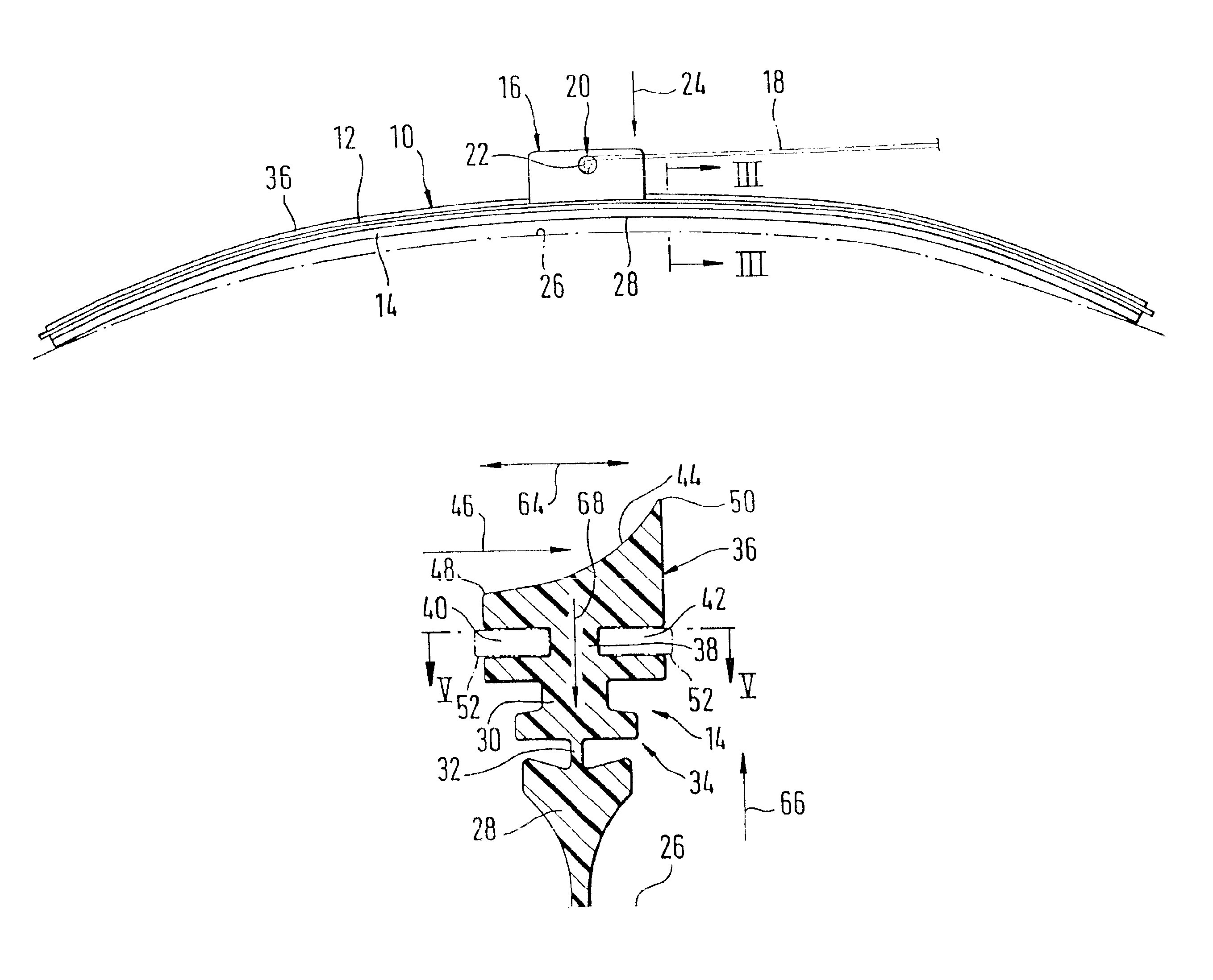
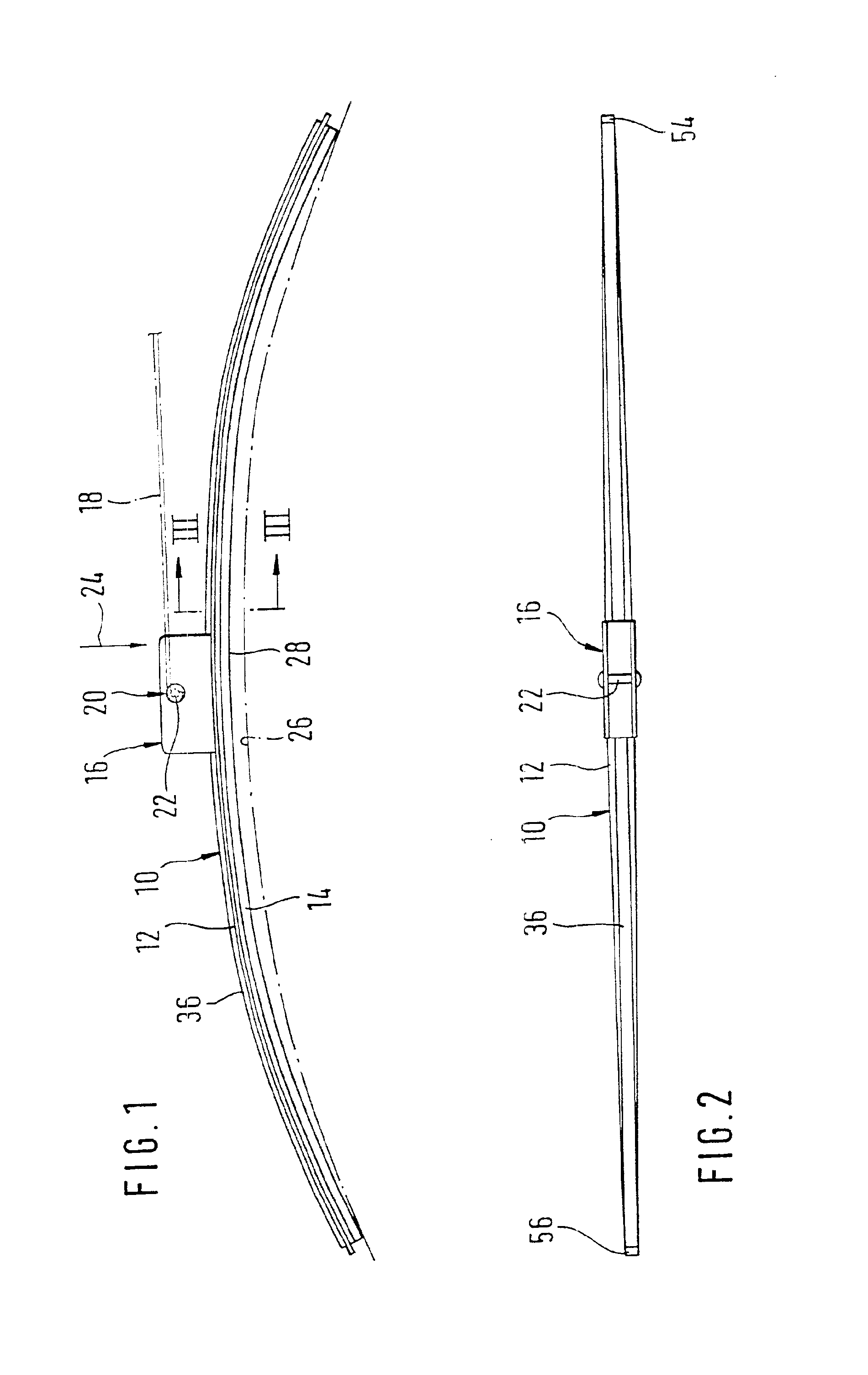
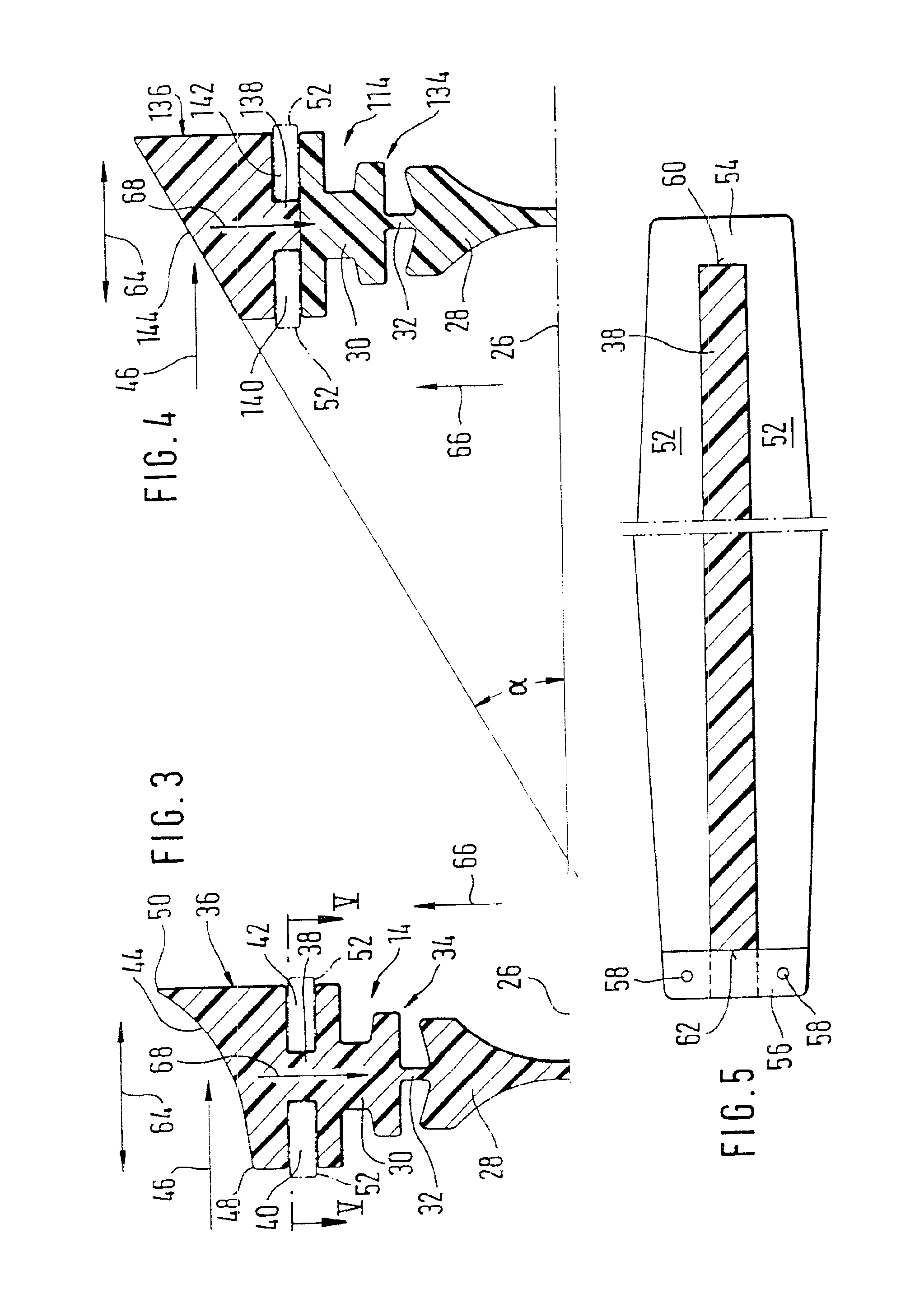
A wiper blade 10 shown in FIGS. 1 and 2 has a multi-part, elongated, spring-elastic support element 12, to which an elongated, rubber-elastic wiper strip 14 is secured longitudinally axially parallel to it. The support element 12 in unloaded condition is curved upper surface 13 which follows its curvature from behind a plane which, when the wiper blade 10 is placed on the window to be wiped, extends parallel to a window surface 26. Furthermore, the support element 12 has a concave lower side 15. The support element 12 also has two legs 17 which have upper sides defining the plane provided by the support element.

A connection device 16 is disposed on the top side of the support element, and with its aid the wiper blade 10 can be detachably connected to a driven wiper arm 18. A hook acting as a counterpart connection means is formed onto the free end 20 of the wiper arm 18 and grasps a pivot pin 22 that belongs to the connection device 22 of the wiper blade. The securing between the wi...


PUM


Abstract

A wiper blade for wiping windows of motor vehicles has an elongated rubber-elastic wiper strip placeable on a window to be wiped and arranged substantially longitudinally axially parallel on a surface of a strip-shaped, spring-elastic support element which is connected with a wiper arm which is spring loaded toward the window and driven transversely to a longitudinal extension of the wiper blade, and a leading-edge face extending longitudinally of the wiper blade and substantially parallel to the window and facing into a wind so as to form an acute angle with the window.

Description

BACKGROUND OF THE INVENTIONThe present invention relates to wiper blades for windows of motor vehicles.In wiper blades the support element is meant to assure the evenest possible distribution of the wiper blade contact pressure on the windows, over the entire swept field swept by the wiper blade. By means of a suitable curvature of the unstressed support element—that is, when the wiper blade is not applied to the wiper blade—the ends of the wiper strip, which in wiper blade operation is pressed entirely against the window, are urged toward the window by the then-stressed support element, even if the radii of curvature of spherically curved vehicle windows differ in every position of the wiper blade. The curvature of the wiper blade must accordingly be somewhat greater than the greatest curvature measured in the swept field of the window to be wiped. The support element thus replaces the complicated support bracket construction, having two spring rails disposed in the wiper strip, of...

Claims


Application Information

Patent Timeline
Patent Type & Authority Patents(United States)
IPC IPC(8): B60S1/38
CPCB60S1/3879B60S1/3808B60S1/3806B60S2001/3836
Inventor KOTLARSKI, THOMASMERKEL, WILFRIEDLEUTSCH, WOLFGANGSCHMIDT, THOMAS
Owner ROBERT BOSCH GMBH
Why Eureka
Try Eureka