Crop recovery machine

a recovery machine and crop technology, applied in agriculture, agricultural tools and machines, baling, etc., can solve the problem of not being able to guarantee the reliable flow of crops, and achieve the effect of improving the conveying process

Inactive Publication Date: 2005-04-05
DEERE & CO
View PDF20 Cites 31 Cited by
  • Summary
  • Abstract
  • Description
  • Claims
  • Application Information

AI Technical Summary

Benefits of technology

If the second rotor can be moved transverse to the flow of the crop, for example, pivoted on arms sliding in guides, it can perform an adequate

Problems solved by technology

The balers described above have the common disadvantage that no reliable crop flow can be guaranteed with

Method used


Image

  • Crop recovery machine
  • Crop recovery machine
  • Crop recovery machine

Examples


Embodiment Construction

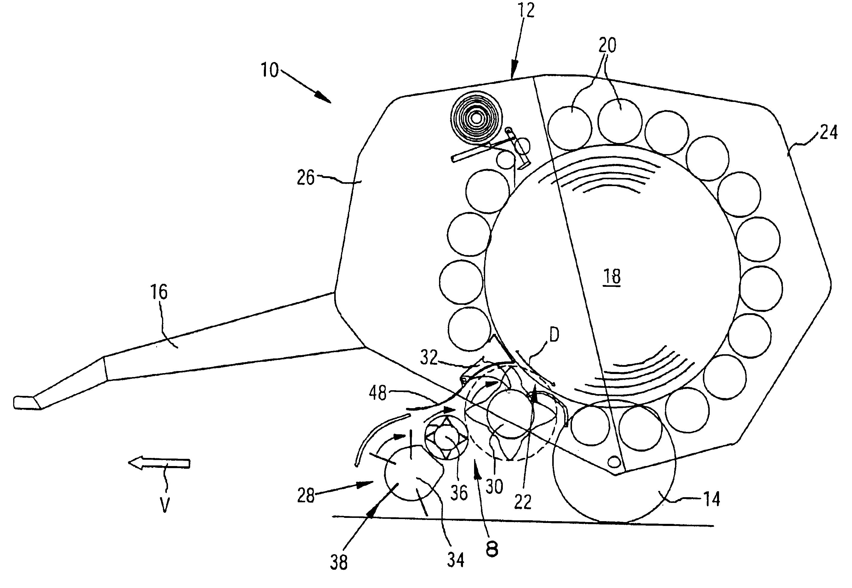
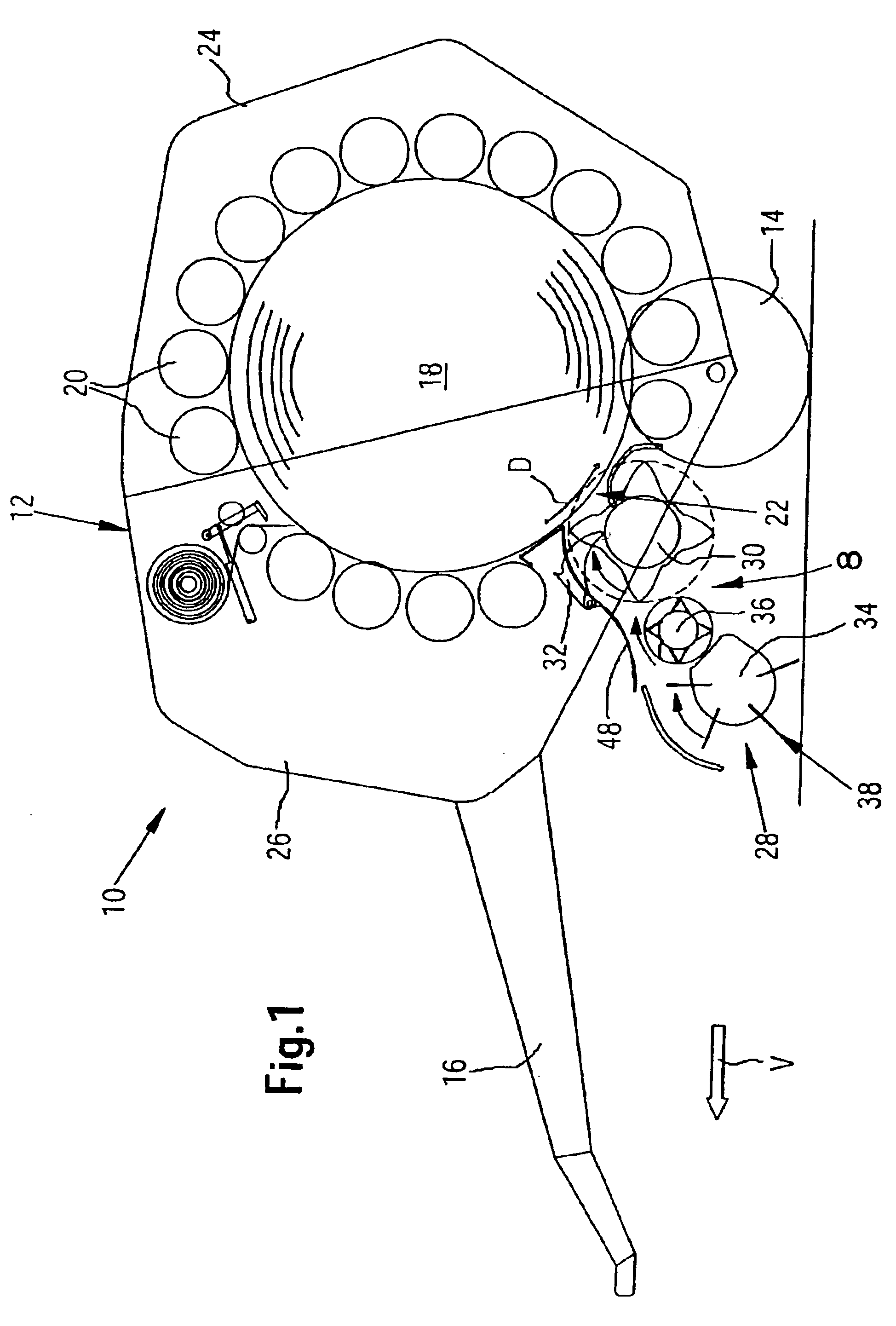
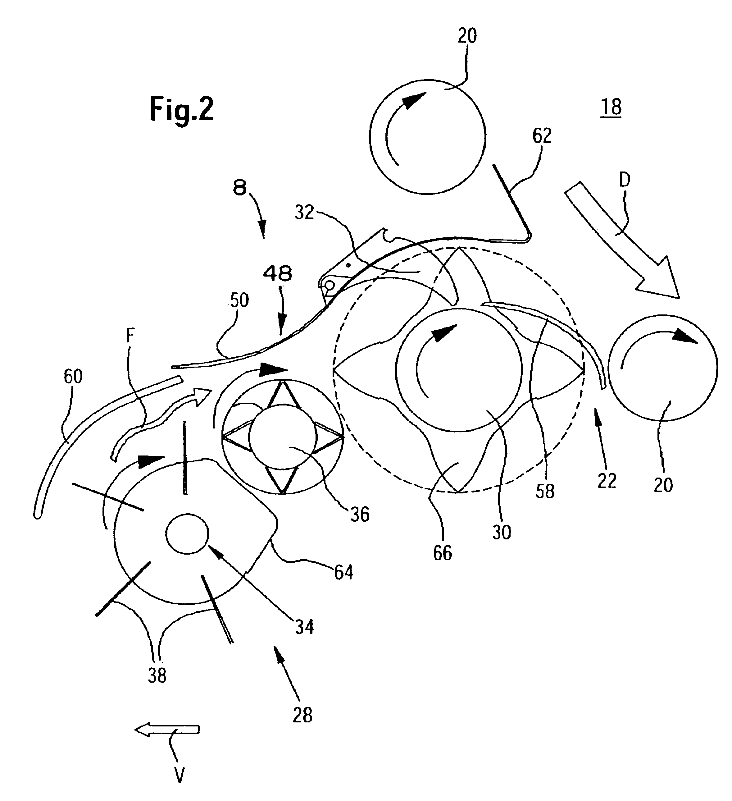
FIG. 1 shows a crop recovery machine in the form of a large round baling press or baler 10 with a crop take-up arrangement 28 at a forward lower side that extends over the entire operating width of the baler 10, and a conveying arrangement 8.

In the present embodiment, the baler 10 is configured as a large round baler, but could also be a self-loading forage box, a large square baler or the like, in which the crop taken up is reduced.

The baler 10 is of a known configuration and includes a frame 12 that is supported by wheels 14 on the ground and that can be coupled by a towbar 16 to a towing vehicle, not shown. Furthermore, the frame 12 carries a baling chamber 18 that is surrounded by rolls 20 and is provided with an inlet 22. The rolls 20 are arranged on a circular arc and include a first plurality of rolls 20 located in a discharge gate 24 that can be pivoted vertically and with a second plurality of rolls 20 located in a rigid housing 26. The direction of rotation of a cylindrica...


PUM


Abstract

A large round baler is provided with a crop take-up arrangement as well as a knife shaft ahead of the inlet of a baling chamber which carries knives that cooperate with blades of a first rotor to cut crop material into pieces before the first rotor delivers the crop directly into the baling chamber. A second rotor is provided between the take-up rotor and the first rotor shaft for narrowing the crop flow from that of the crop take-up arrangement to that of the first rotor. All of the rotors perform an overshot conveying that requires a relatively low drive energy and guarantees a continuous flow of the crop into the chamber.

Description

FIELD OF THE INVENTIONThe invention concerns a crop recovery machine including an arrangement for taking up crop and a conveying arrangement, including an overshot conveying rotor associated with, and for conveying the crop into, an inlet of a crop receptacle.BACKGROUND OF THE INVENTIONA large baler with an arrangement for taking up agricultural cereal crop lying on the ground is known from DE 37 19 845 A1. This large baler is provided with a conveying channel with an intermediate conveyor that is equipped with drivers. Each driver of the intermediate conveyor is associated with one knife of a plurality of knives carried by a knife shaft of a cutting arrangement. The knife shaft conveys the harvested crop as an overshot conveyor, while the intermediate conveyor rotates in the opposite direction to the knife shaft and is arranged at an angle above it.A large round baler with a crop take-up arrangement arranged underneath a baling chamber and a knife shaft conveying as an overshot con...

Claims


Application Information

Patent Timeline
IPC IPC(8): A01F15/00A01F15/10
CPCA01F15/106A01F2015/108A01F2015/107
Inventor LUCAND, PHILIPPEVIAUD, JEANDERSCHEID, DANIEL ERIC
Owner DEERE & CO
Why Eureka
Try Eureka