Connector of hand tool

a technology of connecting rods and hand tools, applied in the field of connecting rods, can solve the problems of inconvenient user removal of the connecting rod, and achieve the effect of enhancing the versatility of the connecting rod

Inactive Publication Date: 2005-04-05
WU KENG HAO
View PDF15 Cites 39 Cited by
  • Summary
  • Abstract
  • Description
  • Claims
  • Application Information

AI Technical Summary

Benefits of technology

A further objective of the present invention is to provide a connector, wherein the connector seat is an independent structure, so that the connector seat can be used to combine with the operation seat of any kinds and types, thereby enhancing the versatility of the connector.

Problems solved by technology

Thus, the socket cannot be detached from the operation seat easily and conveniently, thereby causing inconvenience to the user in removing the socket from the operation seat of the conventional connector.

Method used


Image

  • Connector of hand tool
  • Connector of hand tool
  • Connector of hand tool

Examples


first embodiment

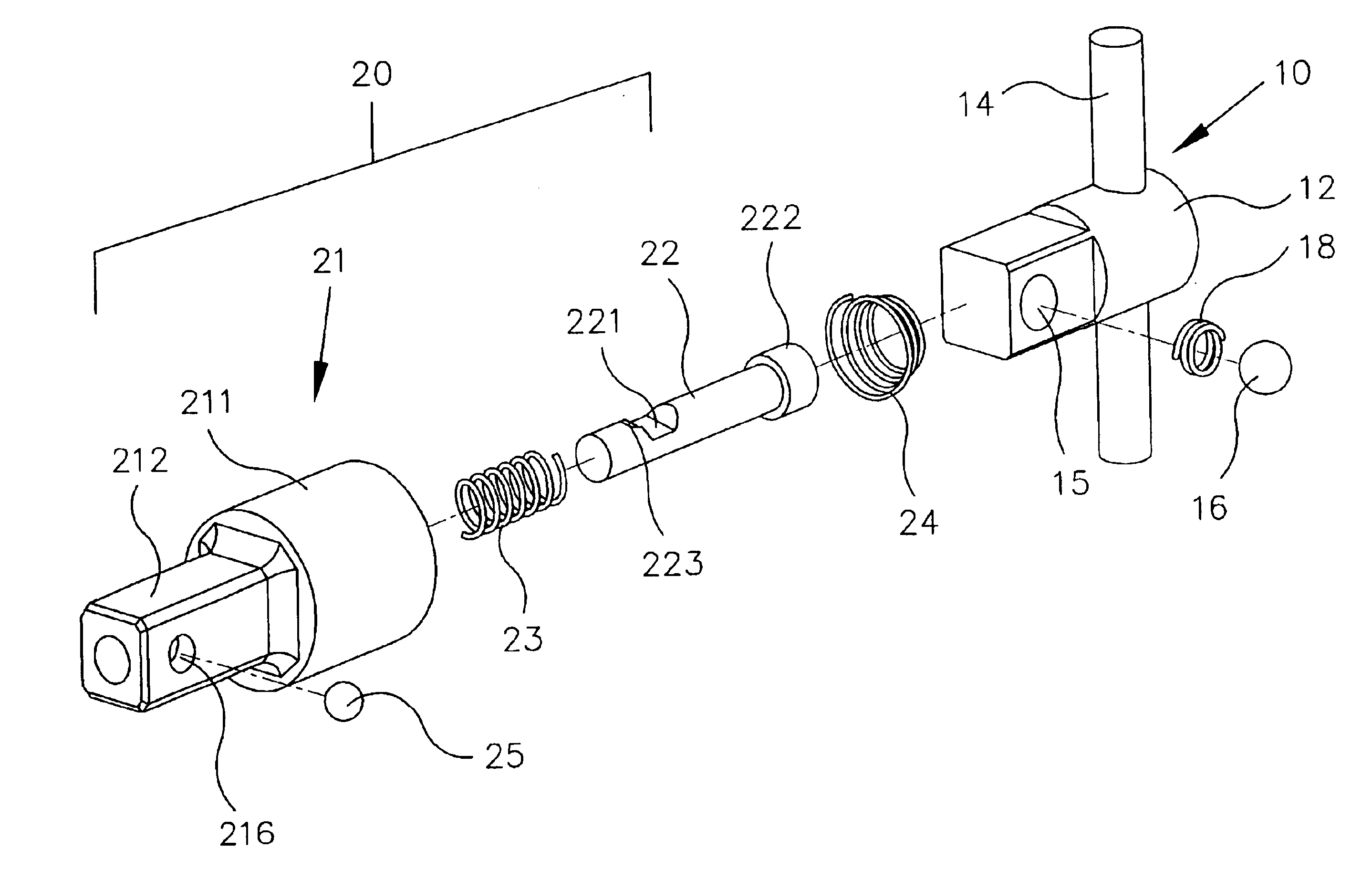
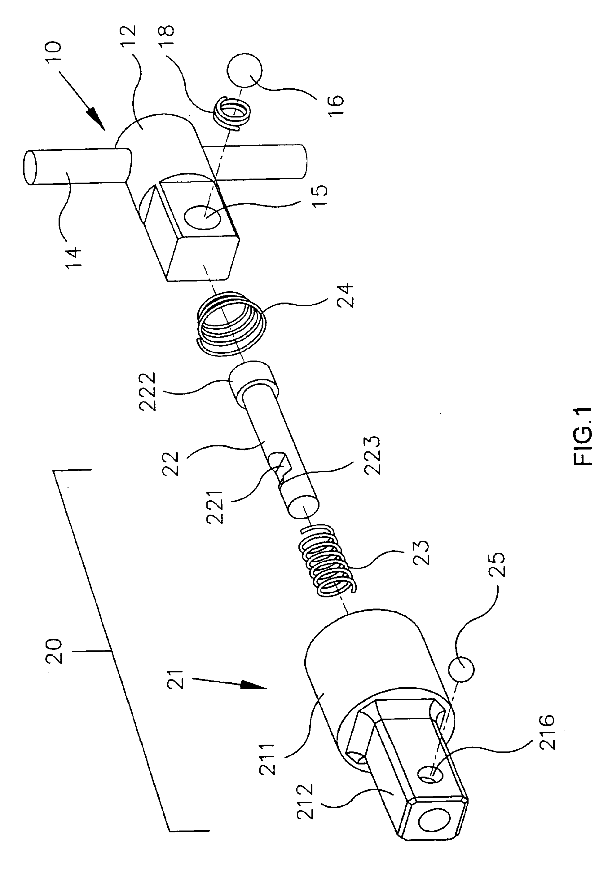
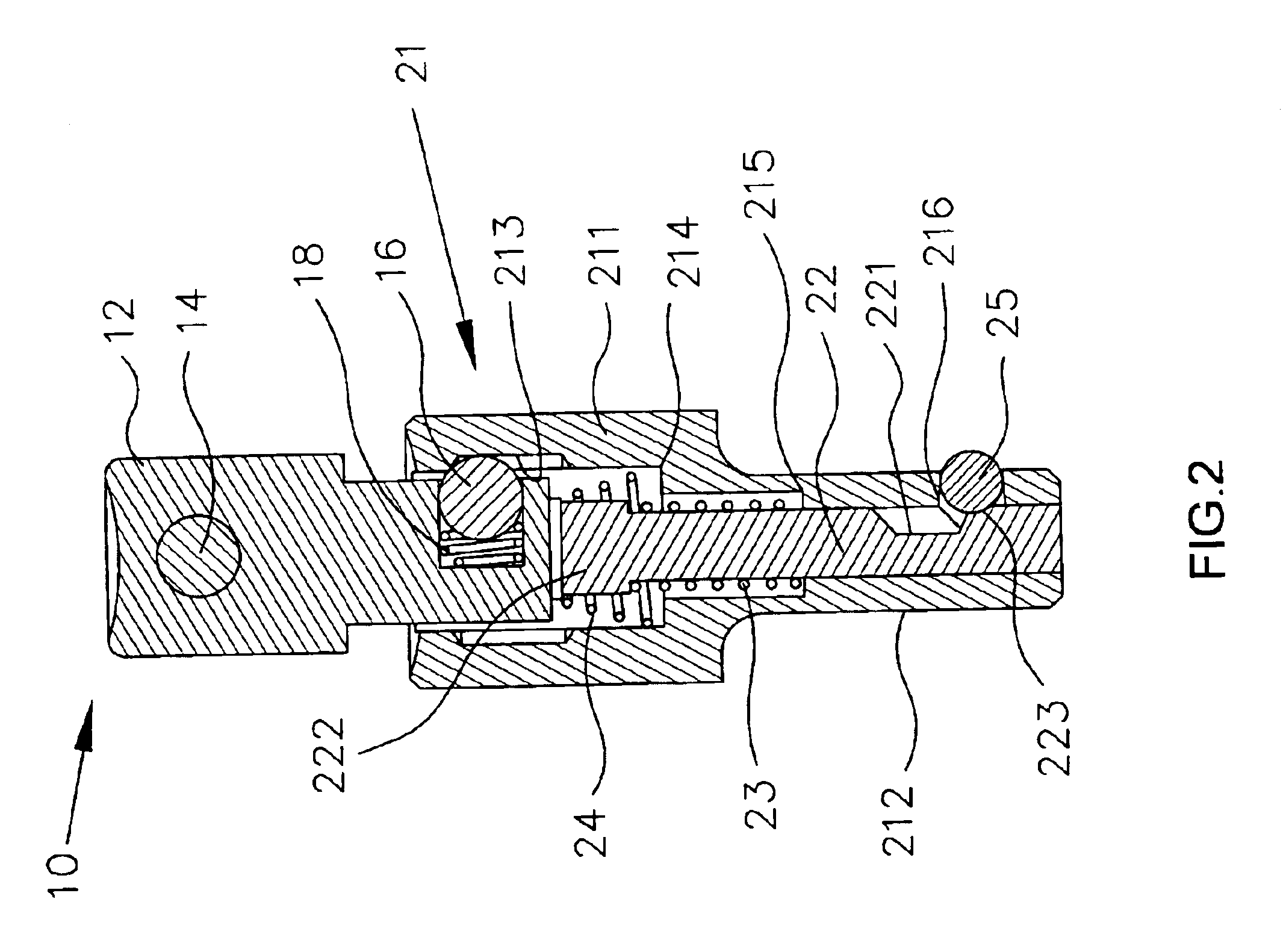
Referring to the drawings and initially to FIGS. 1 and 2, a connector in accordance with the present invention comprises an operation member 10, and a connector seat 20.

The operation member 10 includes an operation seat 12 having a first end formed with a receiving hole 15 for receiving a spring 18 and a retaining ball 16, and an elongated rod 14 extended through a second end of the operation seat 12.

The connector seat 20 is combined with the operation member 10 and includes a main body 21, a movable rod 22, a restoring spring 23, and a cone-shaped spring 24.

The main body 21 of the connector seat 20 is movably mounted on the operation seat 12 of the operation member 10 and has a first end formed with a cylindrical mounting portion 211 and a second end formed with a square receiving portion 212. The mounting portion 211 of the main body 21 of the connector seat 20 has an inner wall formed with an annular slide groove 213, and the retaining ball 16 on the operation seat 12 of the oper...

second embodiment

Referring to FIG. 4, the connector in accordance with the present invention is shown, wherein the operation seat 12A is formed with an elongated guide slot 121A, and the connector further comprises a fixing pin 122A extended through the mounting portion 211A of the main body 21A and the guide slot 121A of the operation seat 12A, so that the operation seat 12A is movable relative to the main body 21A.

third embodiment

Referring to FIGS. 5 and 6, the connector in accordance with the present invention is shown, wherein the mounting portion 211B of the main body 21B has a wall formed with an elongated guide slot 32B to receive and guide the retaining ball 16B of the operation seat 12B, so that the operation seat 12B is movable relative to the main body 21B.


PUM


Abstract

A connector includes a connector seat combined with an operation member and including a main body, a movable rod, a positioning ball, and at least one spring. Thus, the main body is movable relative to the operation seat of the operation member to retract the positioning ball into the receiving cavity of the movable rod, so that the socket can be mounted on and detached from the connector easily and conveniently, thereby saving the manual work.

Description

BACKGROUND OF THE INVENTION1. Field of the InventionThe present invention relates to a connector, and more particularly to a connector for a hand tool, such as the socket, the screwdriver head or the like.2. Description of the Related ArtA conventional connector comprises an operation seat having a first end formed with a receiving hole for receiving a spring and a positioning ball, and an elongated rod extended through a second end of the operation seat. In assembly, when a hand tool, such as a socket or screwdriver head, is mounted on the operation seat of the conventional connector, the inner wall of the socket is locked by the protruding positioning ball, thereby positioning the socket on the operation seat of the conventional connector. In operation, when the socket is mounted on a workpiece, such as a bolt or nut, the elongated rod can be rotated to produce a larger torque so as to screw or unscrew the bolt.However, the inner wall of the socket is locked by the protruding posi...

Claims


Application Information

Patent Timeline
Patent Type & Authority Patents(United States)
IPC IPC(8): B25B23/00
CPCB25B23/0035B25B23/0021
Inventor WU, KENG HAO
Owner WU KENG HAO
Why Eureka
Try Eureka