Electrical connector with deformable insert

Inactive Publication Date: 2005-04-05
BENSON & HEDGES
View PDF28 Cites 26 Cited by
  • Summary
  • Abstract
  • Description
  • Claims
  • Application Information

AI Technical Summary

Benefits of technology

A castellated profile is particularly preferred, as the ridges support the side of the socket insert remote from the clamping means when the socket insert is engaged by the clamping means, and this gives rise to more controlled deformation of the socket insert and hence more secure and efficient electrical

Problems solved by technology

A disadvantage of connectors of this type is that the internal dimensions of the socket (normally the diameter in the case of a socket of circular bore) are fixed.
This creates increased electrical stress when voltage is applied and can lead to difficulty in achi

Method used


Image

  • Electrical connector with deformable insert
  • Electrical connector with deformable insert
  • Electrical connector with deformable insert

Examples


Embodiment Construction

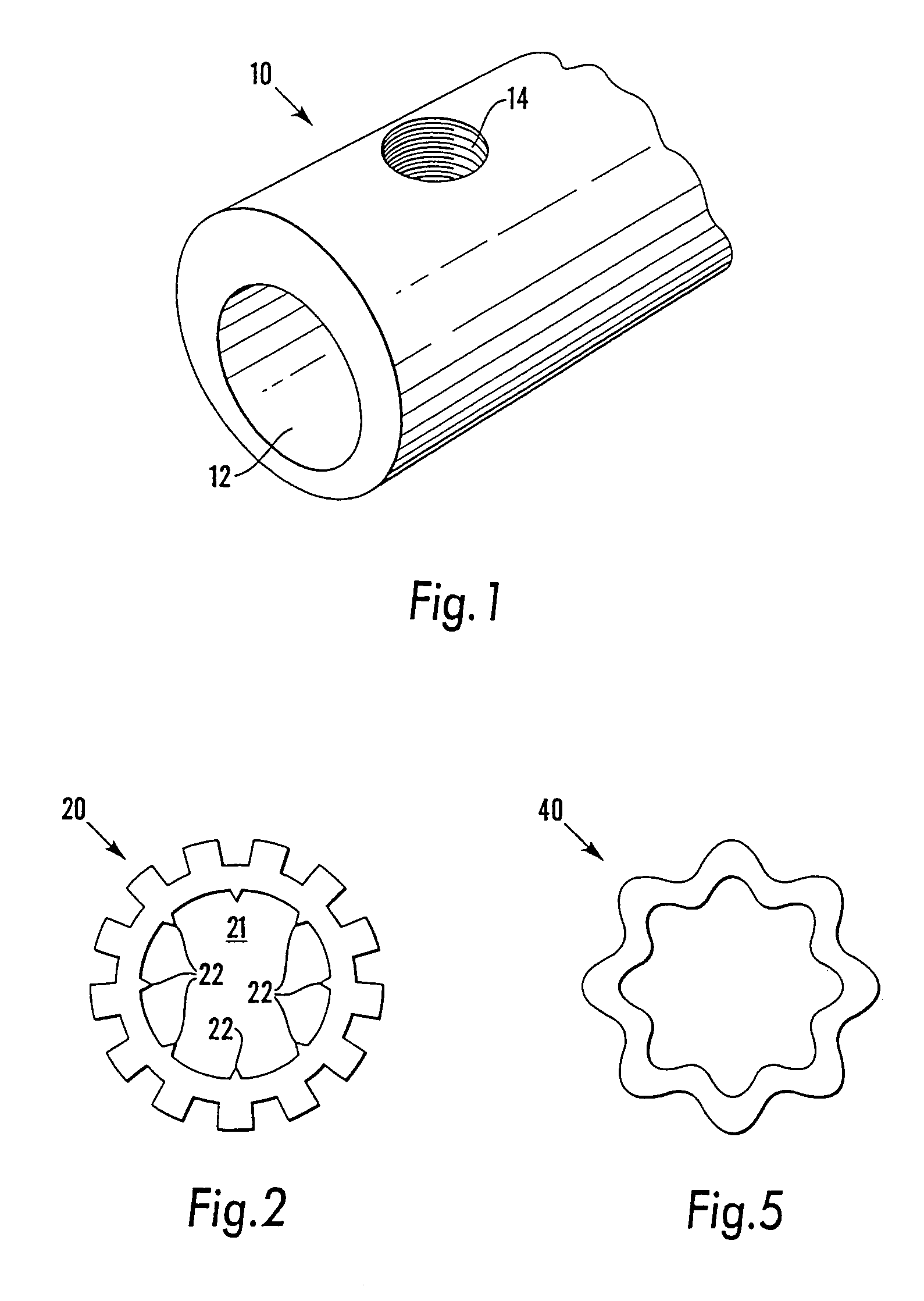
Referring first to FIG. 1, a connector body 10 is formed from aluminium and comprises a tubular socket 12. The portion of the body 10 shown may be formed integrally with one or more similar parts incorporating further similar sockets, eg for end-to-end connection of two conductors. Alternatively, the body 10 may be formed integrally with a fixing flange for termination of the conductor.

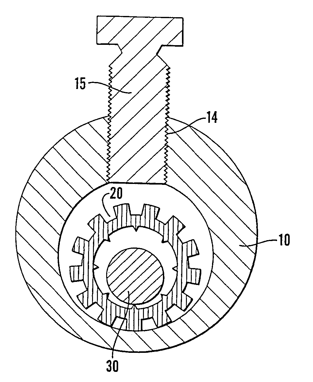
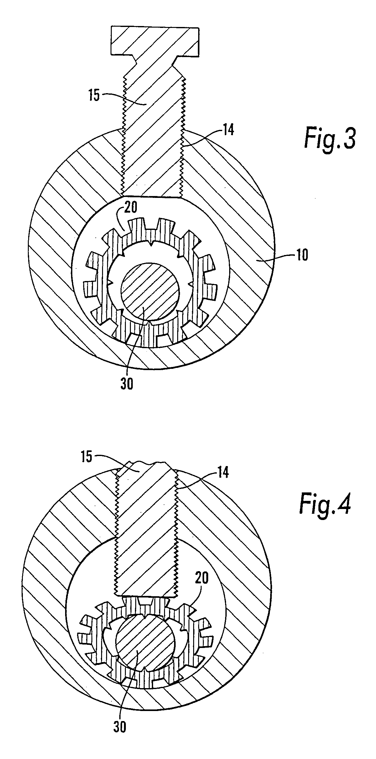
A wall of the body 10 has a threaded bore 14 to receive a shear-head clamping bolt 15 (see FIGS. 3 and 4). The body 10 may be provided with more than one, eg two, such threaded bores 14.

A large diameter conductor may be inserted directly into the socket 12 and clamped using a bolt 15. For use with smaller diameter conductors, however, the socket insert 20 shown in FIG. 2 is used. The insert 20 has the form of an extruded aluminium tube with a castellated profile. The internal bore 21 of the insert 20 is formed with a number of axial teeth 22 which enhance the engagement of the insert 20 with a conduct...


PUM


Abstract

Electrical connectors are provided including a connector body with a tubular socket to receive an electrical conductor. A clamping means is arranged to secure the electrical conductor within the socket. A socket insert fits within the socket so as to reduce the effective size of the socket. The socket insert is tubular and is adapted to be deformed by the clamping means into retaining engagement with the electrical conductor.

Description

FIELD OF THE INVENTIONThis invention relates to improvements in electrical connectors, in particular connectors for the mechanical connection or termination of one or more electrical conductors.BACKGROUND OF THE INVENTIONElectrical connectors comprising a tubular socket into which the end of an electrical conductor is inserted are widely used. Clamping bolts are commonly held in threaded bores in the wall of the socket and are used to fix the conductor to the internal surface of the socket, thereby establishing electrical and mechanical connection between the conductor and the connector.A disadvantage of connectors of this type is that the internal dimensions of the socket (normally the diameter in the case of a socket of circular bore) are fixed. If the conductor inserted into the socket has a diameter substantially less than the internal diameter of the socket then the assembly of socket and conductor will be asymmetrical. This creates increased electrical stress when voltage is a...

Claims


Application Information

Patent Timeline
IPC IPC(8): H01R4/36H01R4/28
CPCH01R4/363
Inventor HOLLICK, DAVID JOHN
Owner BENSON & HEDGES
Why Eureka
Try Eureka