Apparatus for spinal stabilization

Inactive Publication Date: 2005-04-05
HOWMEDICA OSTEONICS CORP
View PDF69 Cites 249 Cited by
  • Summary
  • Abstract
  • Description
  • Claims
  • Application Information

AI Technical Summary

Benefits of technology

These and other unique features of the apparatus disclosed herein and the method of installi

Problems solved by technology

Trauma or developmental irregularities can result is spinal pathologies which limit this range of motion.
However, this configuration is bulky and can cause irritation of the patient's bac

Method used


Image

  • Apparatus for spinal stabilization
  • Apparatus for spinal stabilization
  • Apparatus for spinal stabilization

Examples


Embodiment Construction

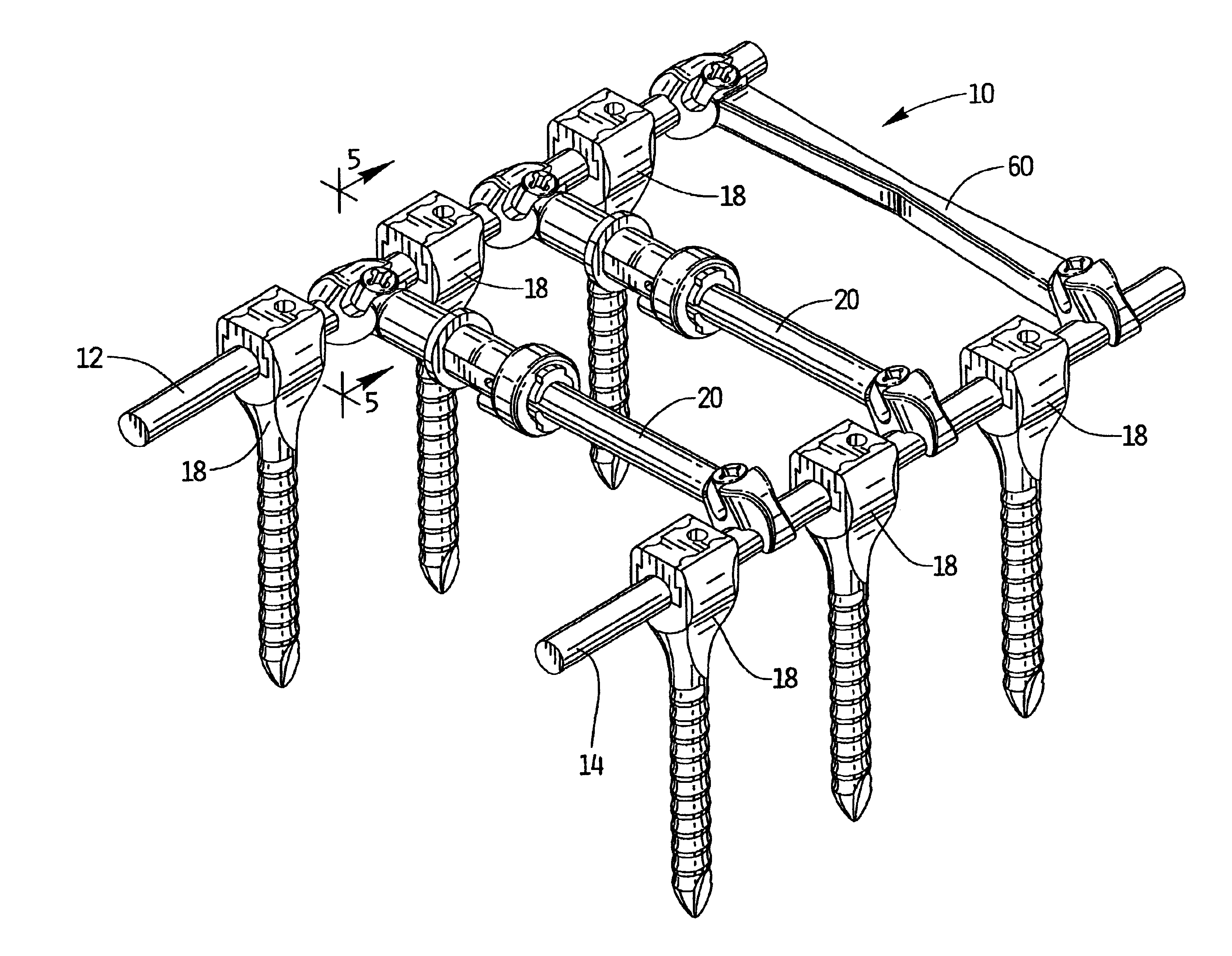
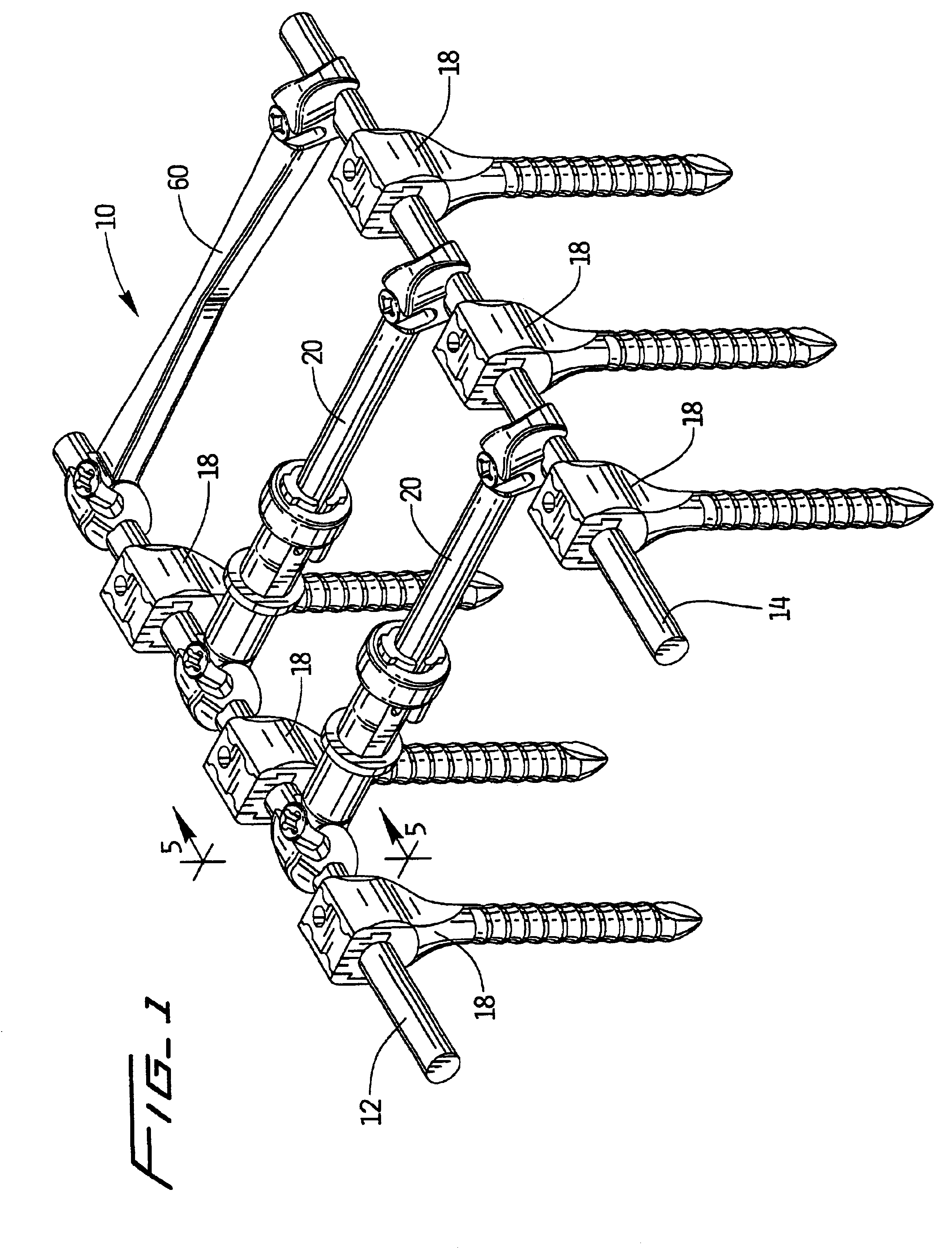
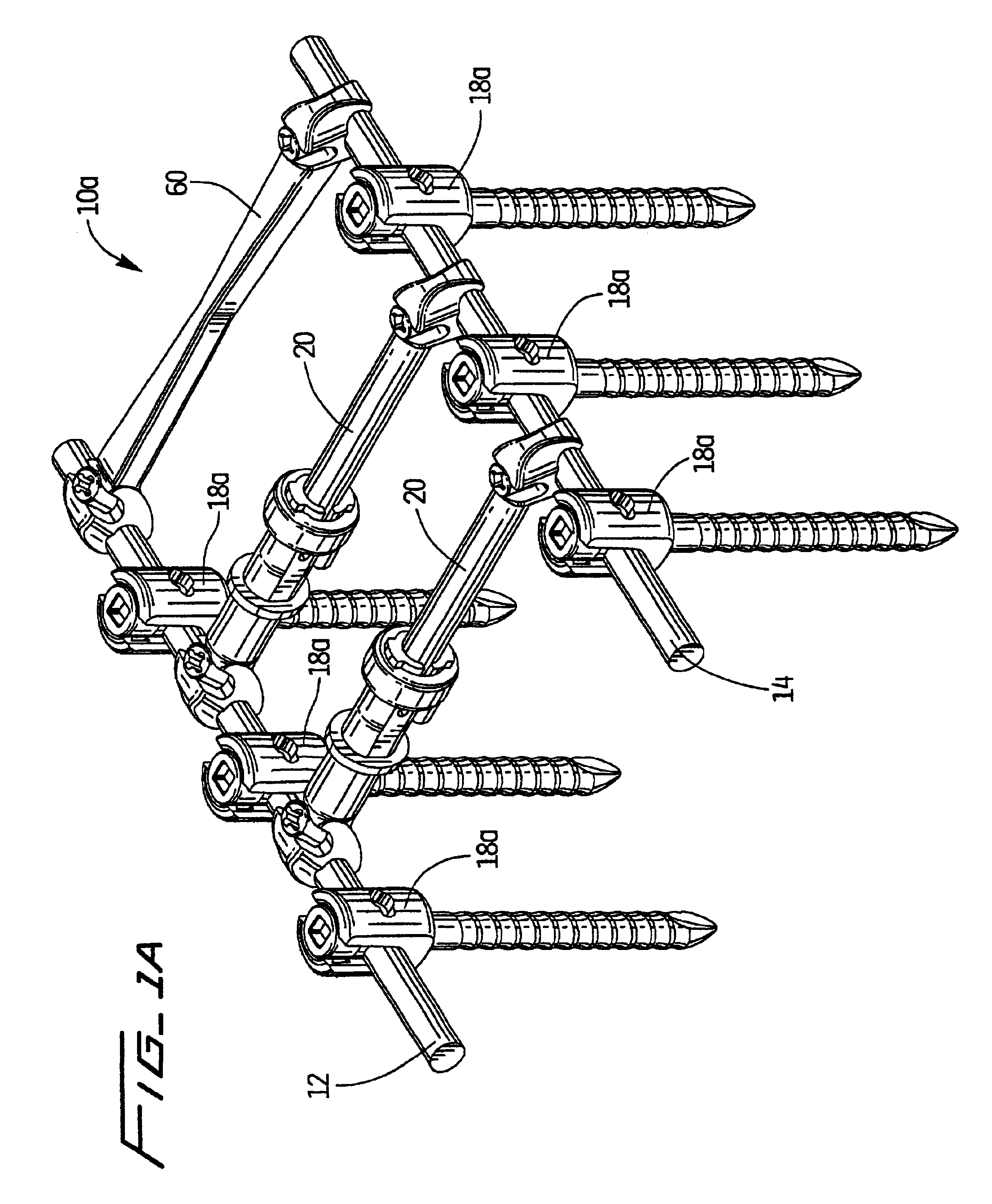
Referring now to the drawings wherein like reference numerals identify similar structural elements of the subject apparatus, there is illustrated in FIGS. 1 and 2a spinal stabilization system constructed in accordance with a preferred embodiment of the subject disclosure and designated generally by reference numeral 10.

Referring to FIG. 1, spinal stabilization system 10 includes a pair of elongated spinal rods 12 and 14. The spinal rods are adapted for parallel deployment on either side of the spinous process, as illustrated in FIG. 2. Spinal rods 12 and 14 are of a conventional type, constructed from a bio-compatible material and having a circular cross-section with a smooth outer surface finish. Spinal rods 12 and 14 are segmentally secured to the bones of the spinous process by a variety of structural components including, for example, bone screws 18.

Bone screws 18 have linear locking mechanisms of the type disclosed in commonly assigned U.S. Pat. No. 5,989,251, the disclosure of...


PUM


Abstract

An apparatus is disclosed for connecting first and second elongated spaced apart spinal rods to one another which includes an elongated body portion, a clamp portion depending from the body portion for engaging a spinal rod, the clamp portion defining a deformable clamp body having opposed clamp arms configured for movement between a first position wherein a spinal rod is received between the opposed clamp arms of the clamp body and a second position wherein the spinal rod is securely engaged by the opposed clamp arms of the clamp body, and structure operatively associated with the clamp body which is configured to effectuate movement of the opposed clamp arms of the clamp body between the first and second positions.

Description

BACKGROUND OF THE DISCLOSURE1. Field of the DisclosureThe subject disclosure relates to implantable spinal stabilization systems for surgical treatment of spinal disorders, and more particularly, to an apparatus for connecting cylindrical spinal rods of a spinal stabilization system to one another across the spinous process.2. Background of the Related ArtThe spinal column is a complex system of bones and connective tissue which protects critical elements of the nervous system. Despite these complexities, the spine is a highly flexible structure, capable of a high degree of curvature and twist through a wide range of motion. Trauma or developmental irregularities can result is spinal pathologies which limit this range of motion.For many years, orthopedic surgeons have attempted to correct spinal irregularities and restore stability to traumatized areas of the spine through immobilization. Over the past ten years, spinal implant systems have been developed to achieve immobilization. ...

Claims


Application Information

Patent Timeline
IPC IPC(8): A61B17/70A61B17/58
CPCA61B17/7052
Inventor NICHOLS, DAVIDFINLEY, ERIC
Owner HOWMEDICA OSTEONICS CORP
Why Eureka
Try Eureka