Cutting apparatus and method for venetian blinds

a technology for venetian blinds and cutting tools, applied in the direction of manufacturing tools, stock shearing machines, door/window protective devices, etc., can solve the problems of increasing the size and complexity of such a machine, requiring a substantial amount of custom process time to custom build blinds, and reducing the efficiency of the custom process. , to achieve the effect of reducing the chance of components falling off and saving tim

Inactive Publication Date: 2005-04-12
TEH YOR CO LTD
View PDF27 Cites 33 Cited by
  • Summary
  • Abstract
  • Description
  • Claims
  • Application Information

AI Technical Summary

Benefits of technology

The present invention is an apparatus for cutting a Venetian blind and a method for operating the apparatus. Typically such Venetian blinds comprise a head rail, a bottom rail, and a plurality of blind slats. The present invention enables an operator to cut all these components in a single stage operation without undue force being required to be exerted by the user.
The blind cutting apparatus includes a body, which defines a head rail opening, at least one blind slats opening, and a bottom rail opening. The blind cutting apparatus further comprises a die for cutting the head rail. The die includes two plates located in a co-planar relationship adjacent to each other, each having a head rail aperture, through which an end of the head rail is passed. The die is located next to the body and at least one of the die plates is rotatable. After an end of a head rail is passed through the body opening and the two head rail apertures, at least one of the plates of the die may be rotated by a drive mechanism such that the rotation causes a shearing action between the two plates thereby cutting the head rail. In a preferred embodiment, the head rail aperture on one of the plates may include tooth-like projections, which assist in cutting the head rail by piercing the head rail, and further lessen the amount of force required.
The blind cutting apparatus also includes a blade assembly, also located next to the body, for cutting the bottom rail and the blind slats. The bottom rail and blind slats are cut by the blade assembly. In particular, the ends of the bottom rail and blind slats are passed through bottom rail and blind slats openings in the body. The blade assembly, which is operatively connected to the drive, is moved along a straight or linear path to intersect and cut off the ends of the bottom rail and blind slats extending through their respective openings in the body. The blade assembly preferably includes at least one guillotine-type blade, but may include more than one blade for cutting the bottom rail and blind slats. The blade assembly of the present invention may also be easily interchanged to accommodate different sizes and shapes of bottom rails. For example, bottom rails often comprise a profile having a shape that has an opening, such as a C-shaped profile or a rectangular profile with a segment of one side of the rectangle removed. Other bottom rails, are shaped having a profile with no opening, such as an oval, rectangle, circle, or various other closed shapes. Depending on the bottom rail to be cut, the different blades or dies for the blade assembly of the present invention can be easily installed and used. The blade assembly and die plates are each driven by the drive mechanism such that the bottom rail and blind slats are cut by the blade assembly at substantially the same time as the cutting of the head rail by the die plates.
Because at least one of the plates of the die is designed to move in a rotational manner to cut the head rail, less force is required to cut the head rail than if a die plate were moved along a linear path. Since less force is required to cut the head rail, the bottom rail and blind slats may be trimmed concurrently with the head rail, without any part of the operation requiring an undue amount of force to be exerted by the user.
The present invention may also include an end guide. This end guide is located adjacent to the blade assembly and is configured to restrict how far the blind components can be passed through their respective openings in the body. In this way, a user of the present invention can accurately measure the amount of the blind components to be trimmed and ensure that the desired amount is cut. In some embodiments, this end guide may be caused to move during the cutting operation such that as the blind components are being cut, the end guide may be moved clear of the components so that the cut pieces may be more easily removed from the machine.
As discussed, the present invention uses a rotationally movable die plate to cut the head rail, while concurrently cutting the bottom rail and blind slats with a guillotine type blade. Because all of the Venetian blind components are cut at approximately the same time, there is a time savings. Since all the blind components are cut at the same time, there is little chance for slippage of the components during the trimming process, which would result in uneven cutting.

Problems solved by technology

This procedure is relatively expensive because the process lacks any economies of scale.
This custom process also requires a substantial amount of time to custom build blinds for each particular window.
As stated, the head rail in a Venetian blind is typically made of a fairly strong metal that is difficult to cut.
Such a power driven system increases the size and complexity of such a machine, as well as increases the expense of the machine.
Also, because a blade is used, operators may experience substantial down time due to the need to change blades when worn out.
While such an arrangement lessens the amount of force exerted during the cutting operation by limiting the number of blind components cut at any one time, additional parts are required to separate the cutting operations, which is inherently more expensive, and prone to breakdowns.
Furthermore, since the cutting does not occur at the same time, there is a heightened potential for one or more of the blind components to shift during the cutting process, and therefore, result in an uneven cut.
Other prior art devices are also limited in the type of bottom rails which can easily be cut.
While they can cut open or C-shaped bottom rails, they have difficulty cutting bottom rails which are closed, i.e., not having an opening.

Method used


Image

  • Cutting apparatus and method for venetian blinds
  • Cutting apparatus and method for venetian blinds
  • Cutting apparatus and method for venetian blinds

Examples


Embodiment Construction

The invention disclosed herein is susceptible to embodiment in many different forms. Shown in the drawings and described in detail hereinbelow are certain preferred embodiments of the present invention. The present disclosure, however, is an exemplification of the principles and features of the invention, but does not limit the invention to the illustrated embodiments.

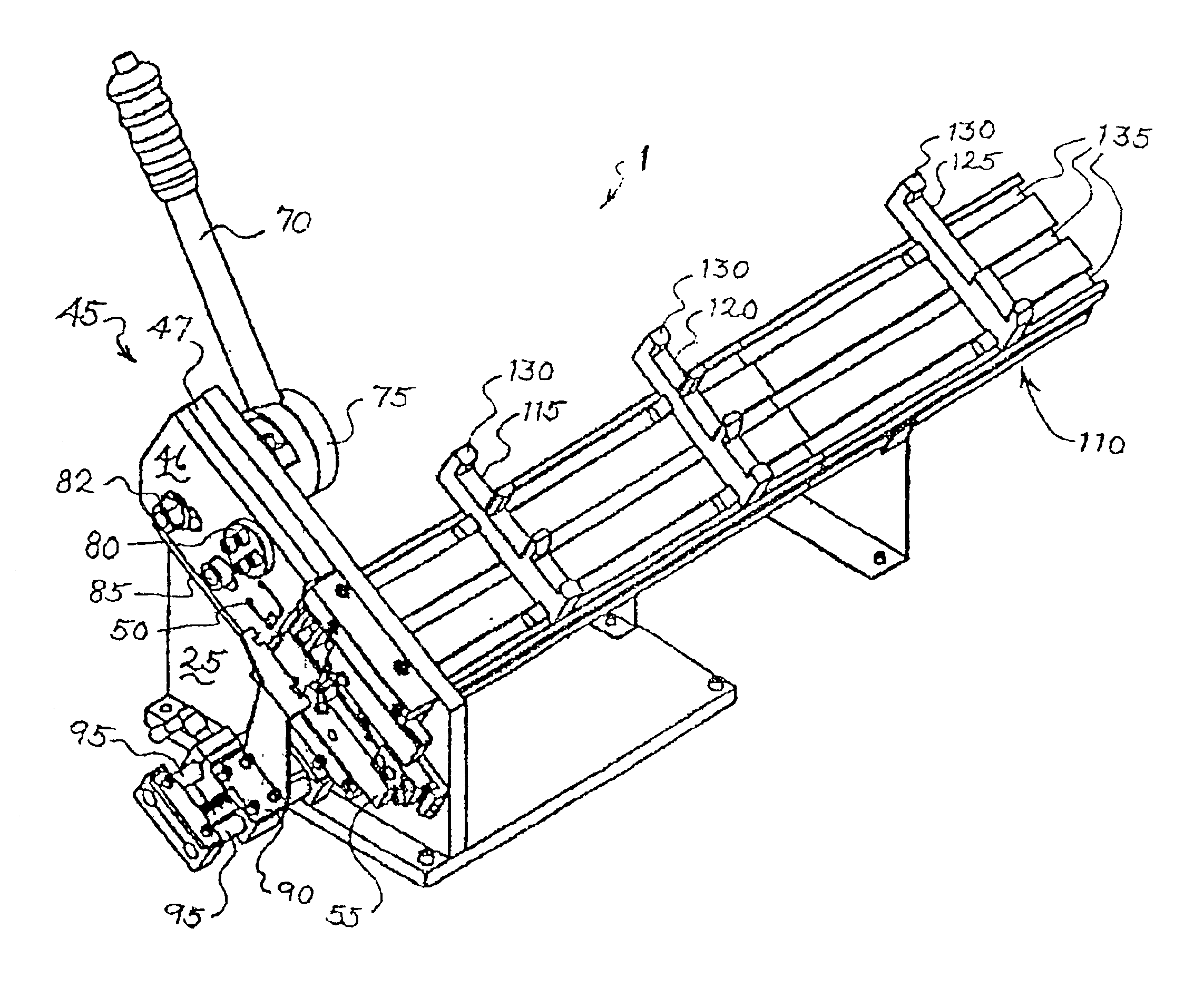
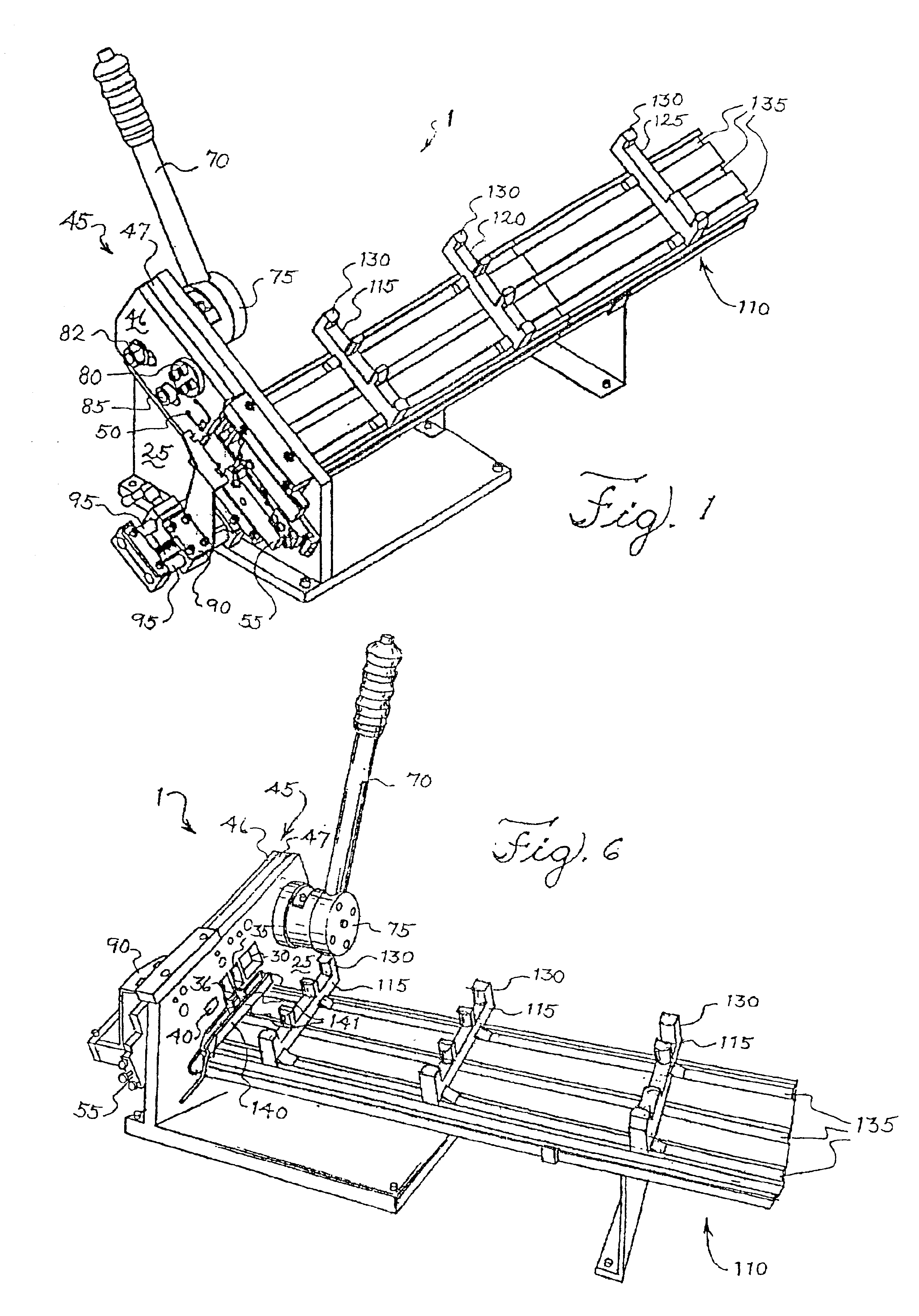
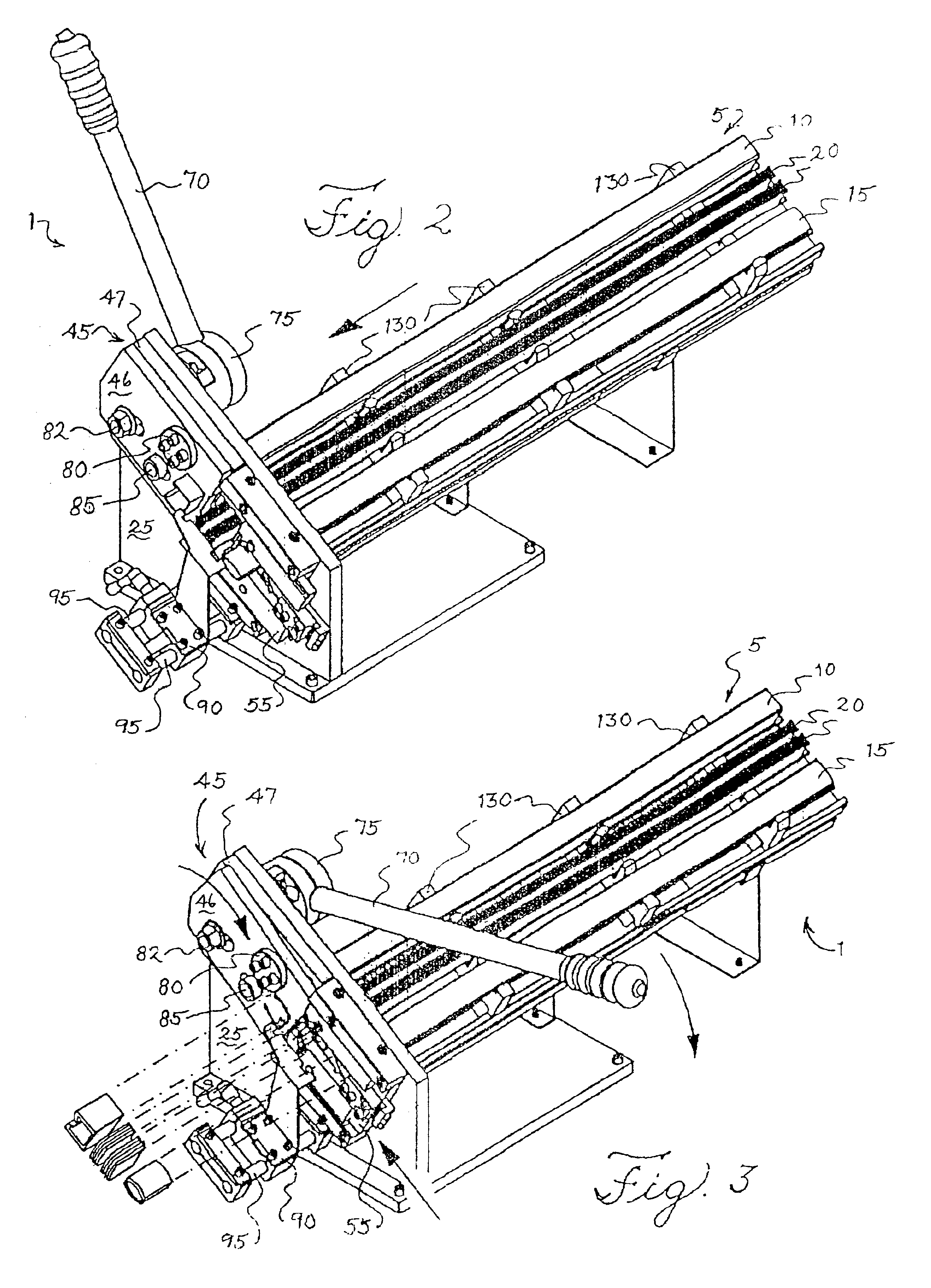
Referring to FIGS. 1 and 2, an embodiment of a Venetian blind cutting apparatus 1 suitable for trimming the components of a Venetian blind 5, such as the head rail 10, the bottom rail 15, and a plurality of blind slats 20 according to the present invention is shown. Also shown in FIGS. 1 and 6 is a body 25 having a head rail opening 30, blind slat openings 35, 36, and a bottom rail opening 40. The bottom rail opening 40 is preferably configured to hold the bottom rail 15 flat so it may be cut along its long cross-sectional axis such as shown in the FIGURES, from front to back.

Located adjacent to the body 25 is a die 45...


PUM

PropertyMeasurementUnit
lengthaaaaaaaaaa
timeaaaaaaaaaa
shapeaaaaaaaaaa

Abstract

A cutting machine for a Venetian blind comprising a head rail, a bottom rail, and a plurality of blind slats. The cutting machine comprises a body defining a head rail opening, a bottom rail opening, and at least one blind slat opening, a plate for cutting the head rail, a blade assembly for cutting the bottom rail the blind slats, and a drive mechanism. The drive mechanism is operatively connected to the plate and the blade assembly causing the plate to cut the head rail while, at the same time, causing the blade assembly to cut the bottom rail and the blind slats.

Description

FIELD OF INVENTIONThis invention relates to a cutting apparatus for Venetian blinds and a method for using the apparatus. In particular, this invention relates to a cutting apparatus that can simultaneously cut the ends of the components of a typical Venetian blind, namely, the head rail, bottom rail and blind slats, in one operation.BACKGROUND OF INVENTIONVenetian blinds are a well known covering for windows. Venetian blinds typically include a head rail, a bottom rail, and a plurality of blind slats. The head rail is usually made from a relatively strong and rigid metal, whereas the bottom rail and blind slats are made from thinner pieces of aluminum. Each of these blind components are designed to extend horizontally across a window space.Window spaces, however, are built in a myriad of different widths. Therefore, there is a need for many different widths of Venetian blinds to suit the differing widths of window spaces. For many years it has been the practice to manufacture Venet...

Claims


Application Information

Patent Timeline
Patent Type & Authority Patents(United States)
IPC IPC(8): B23D23/00E06B9/26E06B9/266B23D15/06
CPCE06B9/266B23D23/00Y10T83/0586Y10T83/9447Y10T83/04Y10T83/8834Y10T83/416Y10T83/404Y10T83/42
Inventor HUANG, CHIN-TIENYU, FU-LAI
Owner TEH YOR CO LTD
Why Eureka
Try Eureka