
Mixing valve with graduated temperature modulation

a technology of temperature modulation and mixing valve, which is applied in the direction of transportation and packaging, process and machine control, instruments, etc., can solve the problems of substantial temperature changes, and difficult to obtain just the right temperature, so as to increase the hot or cold water component of the overall water stream, increase the outlet flow, and increase the effect of temperature control

Inactive Publication Date: 2005-04-12
FB GLOBAL PLUMBING GRP LLC
View PDF8 Cites 25 Cited by
  • Summary
  • Abstract
  • Description
  • Claims
  • Application Information

AI Technical Summary

Benefits of technology

A primary purpose of the invention is to provide a mixing valve assembly with a tapered hot or cold water outlet which provides a smooth and graduated mixed water range.
Another purpose of the invention is to provide a mixing valve assembly which minimizes the differences between outlet streams of different temperatures, and in particular, minimizes the differences between the full hot water flow rate and the mixed water flow rate.

Problems solved by technology

However, most water users favor a mixed temperature outlet stream which is less tractable to obtain.
Obtaining just the right temperature is difficult because the desired mixed temperature range position is very narrow resulting in substantial temperature changes in even an incremental rotational movement.
If the user does not rotate enough, the water is still too cold, but if the user rotates too much the resulting hot water stream can injure or blister the skin of the water user.
Even where no injury occurs, sudden changes in temperature of any kind are inconsistent with comfortable and soothing shower experience desired by users.
There is also a tendency for mixing valves to cause stacking.
Another drawback of current mixing valves is the noticeable difference in flow rates between the full cold water, mixed water and full hot water outlet streams.
So, noticeable decreases in the flow rate and thus the water pressure represents an undesirable change to the user.

Method used


Image

  • Mixing valve with graduated temperature modulation
  • Mixing valve with graduated temperature modulation
  • Mixing valve with graduated temperature modulation

Examples


Embodiment Construction

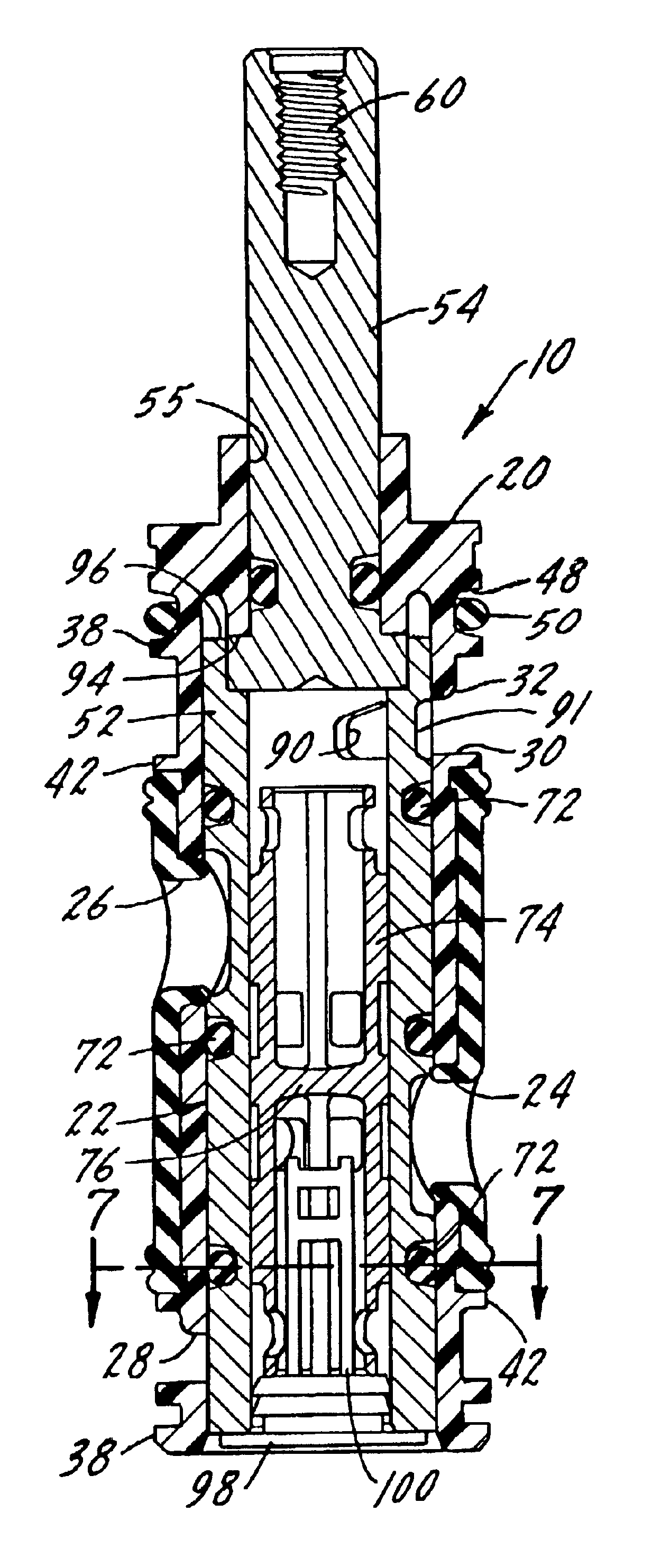
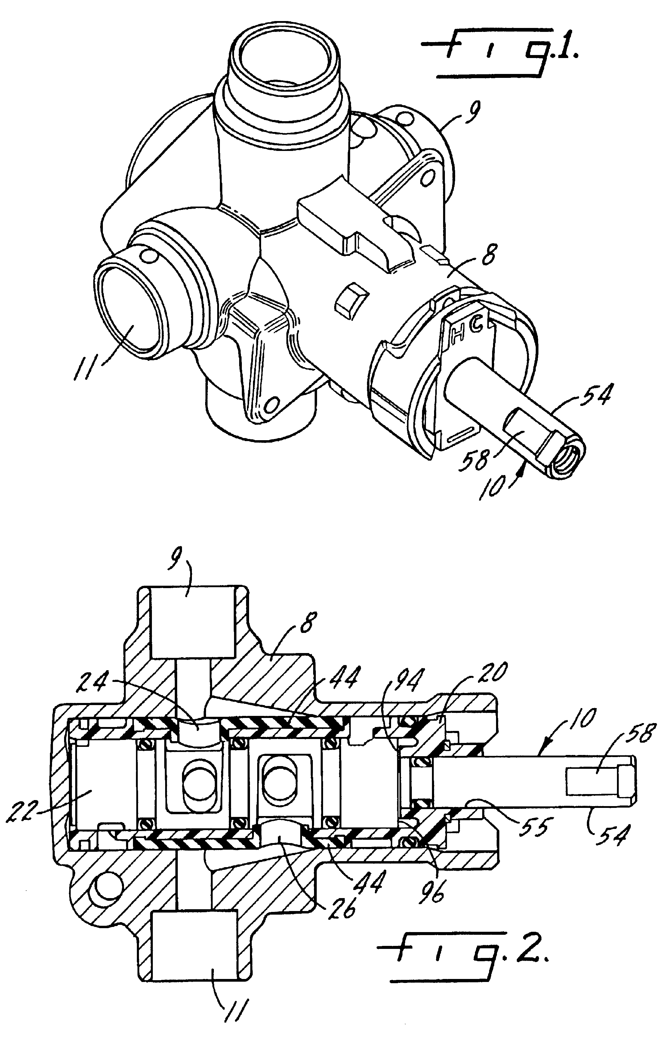
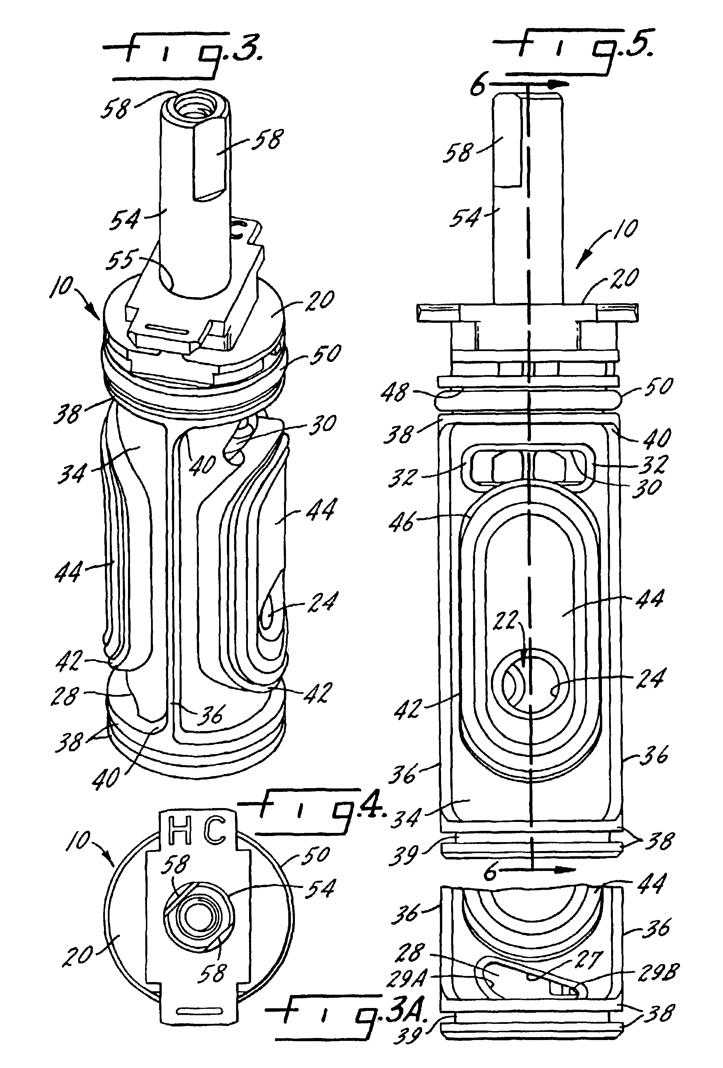
As illustrated in FIGS. 1 and 2, the present invention includes a mixing valve assembly 10 which is insertable into a valve housing 8 with a cold water inlet port 9 and a hot water inlet port 11. The valve housing 8 is similar to that described in U.S. Pat. No. 4,469,121, which is incorporated herein by reference, assigned to Moen Incorporated and sold under the trademark Posi-Temp®. The valve assembly 10 includes a generally cylindrical sleeve 20 and a rotatable non-reciprocal valve member 22 positioned therein. The sleeve 20 has a cold water inlet port 24 and a hot water inlet port 26 which are axially spaced and radially non-aligned. A cold water outlet port 28 and a hot water outlet port 30 are radially non-aligned and are peripherally located from the sleeve cold and hot inlets 24, 26. As illustrated in FIGS. 3-13, at least one of the sleeve cold or hot water outlet ports 28 and 30 has a graduated or tapered portion.

In FIGS. 3-5, the sleeve cold water outlet port 28 has a taper...


PUM


Abstract

A valve assembly for mixing hot and cold water includes a generally cylindrical sleeve having hot and cold inlets and outlets and a rotatable non-reciprocal valve member positioned therein to control the mixture of hot and cold water in the outlet stream. The valve member has a hollow stem tube having hot and cold inlet and outlet ports which are rotatably engageable with the hot and cold inlets and outlets of the sleeve. The sleeve hot water outlet is generally larger than the sleeve cold water outlet. The sleeve and stem tube inlets and outlets are not limited to a particular shape and / or geometry. The fluid engagement between the sleeve hot and cold water outlets and the stem tube hot and cold water outlets provides a large mixed water temperature range.

Description

BACKGROUND OF THE INVENTIONThe present invention relates to mixing valve, particularly mixing valves for kitchen or bath sinks, showerheads, tub spouts and shower-tub combinations. Current mixing valves provide a valve control member that regulates the temperature of the water. During use, the mixing valve can be rotated by the user from an off position through cold water, mixed water and hot water positions. The rotational position of the valve control member determines how much hot or cold water comprises the water outlet stream.Mixing valves generally provide for either all cold water or all hot water streams without difficulty. During operation, a cold stream is easily obtained by incrementally rotating the mixing valve from an off position until a cold water stream is obtained. Similarly a hot water stream is easily obtained by fully rotating the mixing valve until the mixing valve can no longer rotate. However, most water users favor a mixed temperature outlet stream which is ...

Claims


Application Information

Patent Timeline
IPC IPC(8): F16K11/085F16K11/076F16K11/02F16K11/06F16K11/00G05D11/00
CPCF16K11/076F16K19/003F16K11/0856Y10T137/86823Y10T137/2514Y10T137/87249Y10T137/7668
Inventor DEMPSEY, JAMES F.HOLZHEIMER, JOHN C.KESTI, MATT R.FEHLNER, MATTHEW R.GARVIN, BRYAN
Owner FB GLOBAL PLUMBING GRP LLC
Learn More