

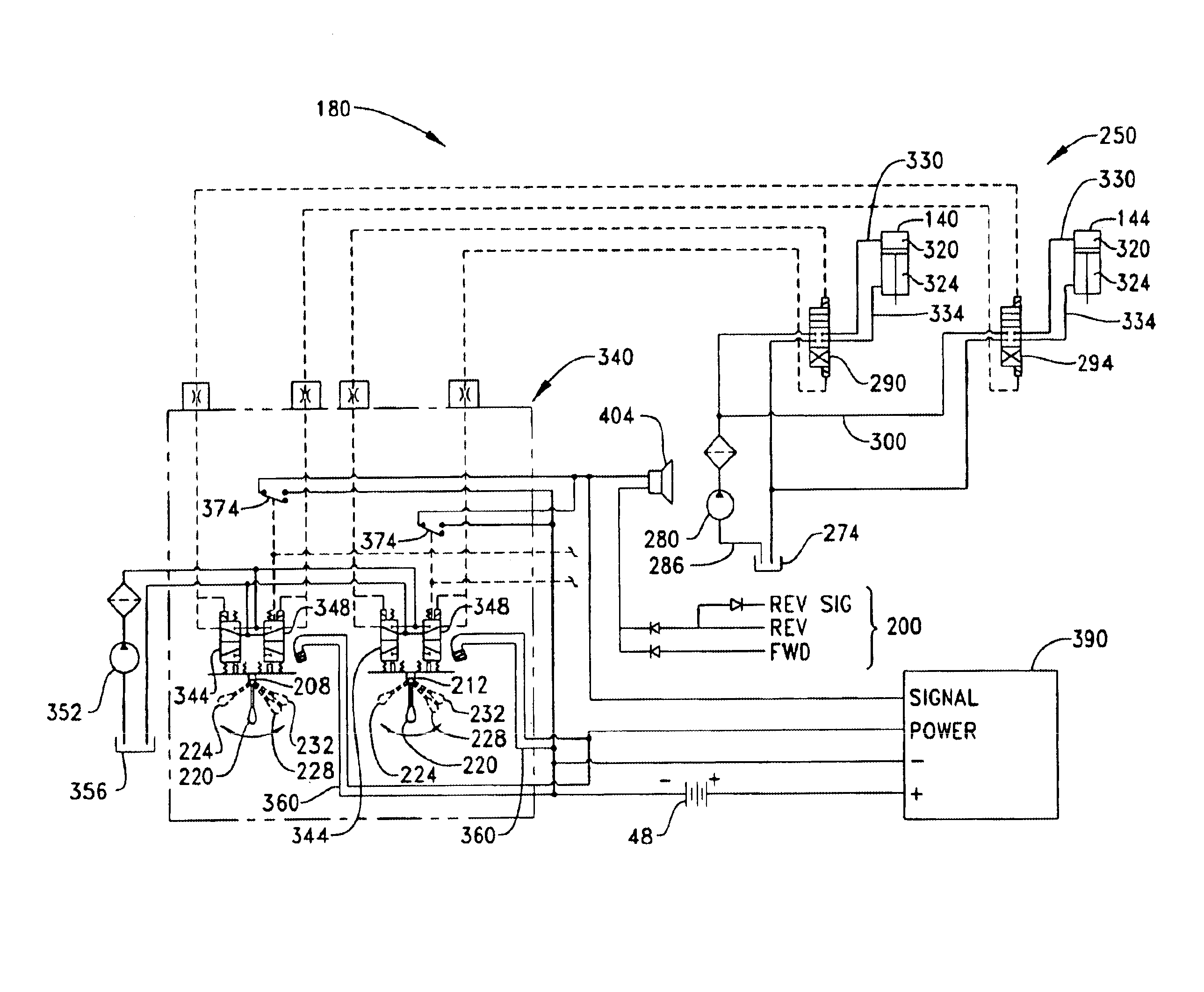
Pilot hydraulic control for a pair of stabilizer legs on a backhoe loader machine
- Summary
- Abstract
- Description
- Claims
- Application Information
AI Technical Summary
Problems solved by technology
Method used
Image

Examples
Embodiment Construction
While the invention is susceptible to various modifications and alternative forms, a specific embodiment thereof has been shown by way of example in the drawings and will herein be described in detail. It should be understood, however, that there is no intent to limit the invention to the particular form disclosed, but on the contrary, the intention is to cover all modifications, equivalents, and alternatives falling within the spirit and scope of the invention as defined by the appended claims.
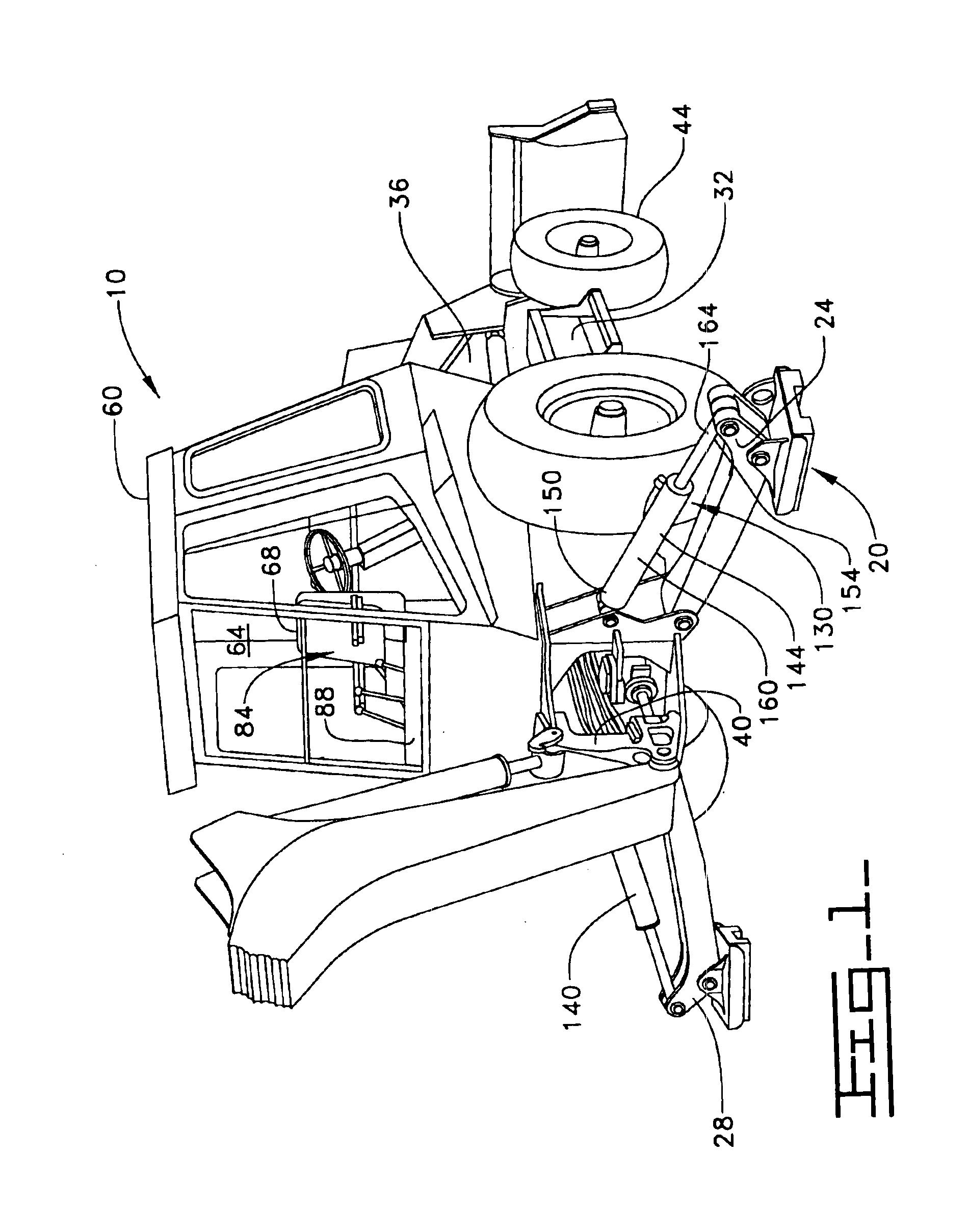
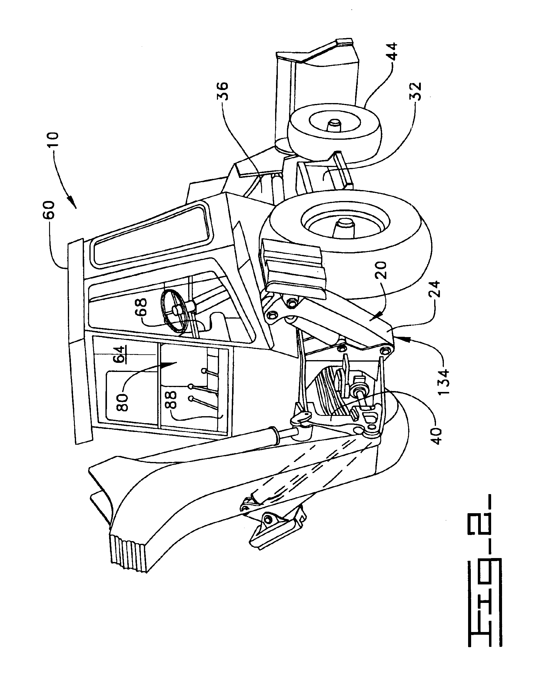
Referring to FIGS. 1-2, a work machine 10, such as a backhoe loader, is shown incorporating an extension and retraction system 20 for a pair of stabilizer legs 24,28. Although the present invention is shown in operative association with a backhoe loader, it should be understood that the present invention may be incorporated on any suitable work machine 10.
Referring now to FIGS. 1-4, the backhoe loader 10 includes a machine frame 32 with front and rear end portions 36,40 supported for travel b...
PUM
 Abstract
Description
Claims
Application Information